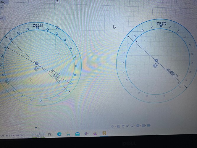
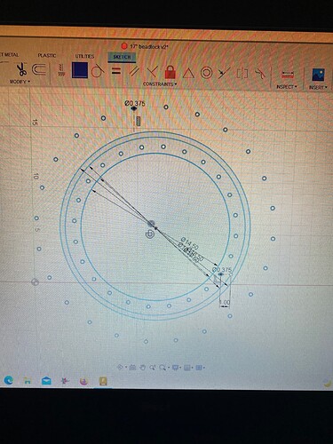
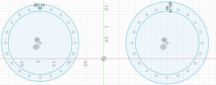
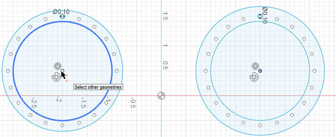
Is there a way I can lay these two parts on top of each other and make sure the holes line up ?
Since they would need to be on the same layer to use the coincidence constraint, this does cause a little conundrum. Once pasted/moved, I don’t know how you would select the one to pull it back apart.
…interesting.
Well, I would save the entire thing as a copy first. It could be on this same sketch. Just move it out of the way. Now select one of the images and pick the centers to be coincident. If you only see one set of holes, it is matched up perfectly. The one image should move on top of the other. To reverse, use the back up (undo) arrow.
That kinda works ? Now it shows the holes around the outside of both drawings
Some how there was a copy that expanded the size. That should not have happened. Definitely undo that.
I thought of another way of selecting. Create a selection set. Select all of one circle and then right click and pick “create selection set.” Now select the whole thing again and do the coincidence points.
Edit: All of the data needs to be constrained to the center points of each drawing. Once you pick the center point and have it a coincident with the other, they match up perfectly. I just did it.
So when you draw the circles, always start in the center. When you make your initial hole in the rim, you will then create the circular array with the center point of the larger circle. If you do that with both figures it will work.
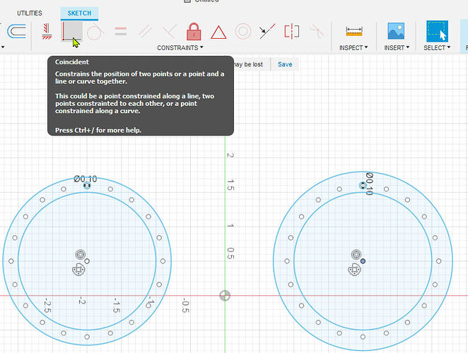
Select center point of one and click the coincident constraint:
Now select the other image’s center:
Result:
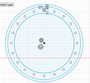
it still just stretches the holes out. its weird
ahhh i see… i did go off of the outside circle for the small holes because it was the easiest way to get them where i needed them
You can make your first hole that way but when you do the array, you need to pick the center of the large circles. If you see a constraint being made with your first hole, delete it (the constraint) before doing the array.
Edit: I see what you did…that dimension line. Delete that dimension line before doing the array. You can confirm the location of the hole with “measure”. Once you know everything is right, add the dimensions back in.
The other way would be to copy one of the images and then change the outer circles and you will know that your holes line up. But, once again, if you tie one of the holes with a dimension line to a circle and you change that circle, it will move the holes.
thank you for your help i got it!
one more question now that i have you here. when i go to extrude it now, only the original hole extrudes. what did i do wrong?
Could you include a picture? Sounds like a break somewhere. Are the holes green or blue before you try to extrude? You want blue. And when you Hoover with the mouse, move it around until all the lines/corcles turn black before you left click.
i figured it out. i missed the part where you said delete the constraint on the first hole.
I live streamed a workflow for this so one flange is driving the holes of the other flange so it is impossible to get them out of alignment.
Starts about 6 minutes into the video
here is a F3D of the example
flange example.f3d (145.0 KB)
Amazing! I had figured that you would do something related to “projection,” which is an area that I have not really grasped yet. Thank you for weighing in on this.
Edit: So I see by using the off-set construction line you are both keeping the holes dependent on the center plus you are being able to accurately measure from the one circle.
Different question: Why did his second set of holes go so crazy when he did the first attempt to line them up with “coincidence” constraint? Nothing suggested that the holes would move in such a major magnitude, that I can see.
There is a parallel constraints and the top on the dot red construction lines attached to the black point dot and at the bottom the coincident constraint at the bottom right attach to another black set off by one inch.
These black points have other rules applied to them because of the constraints you are giving it so the result is not as expected.
if I had the original F3D I am sure we could pinpoint it.
Projection might be one of the most powerful tools in Fusion 360, especially once you start working on assemblies.
Could you not just delete one of them and use “Mirror” to create an exact replica next to the original?
You’d just have to draw a temporary line next to the original as a mirror axis.
I want to learn it, but it is just not clicking yet. I have seen numerous examples where Tin uses it and I am amazed
Thanks for the effort you made to answer this issue! Your voice sounds familiar. Do you perhaps have a youtube channel?
