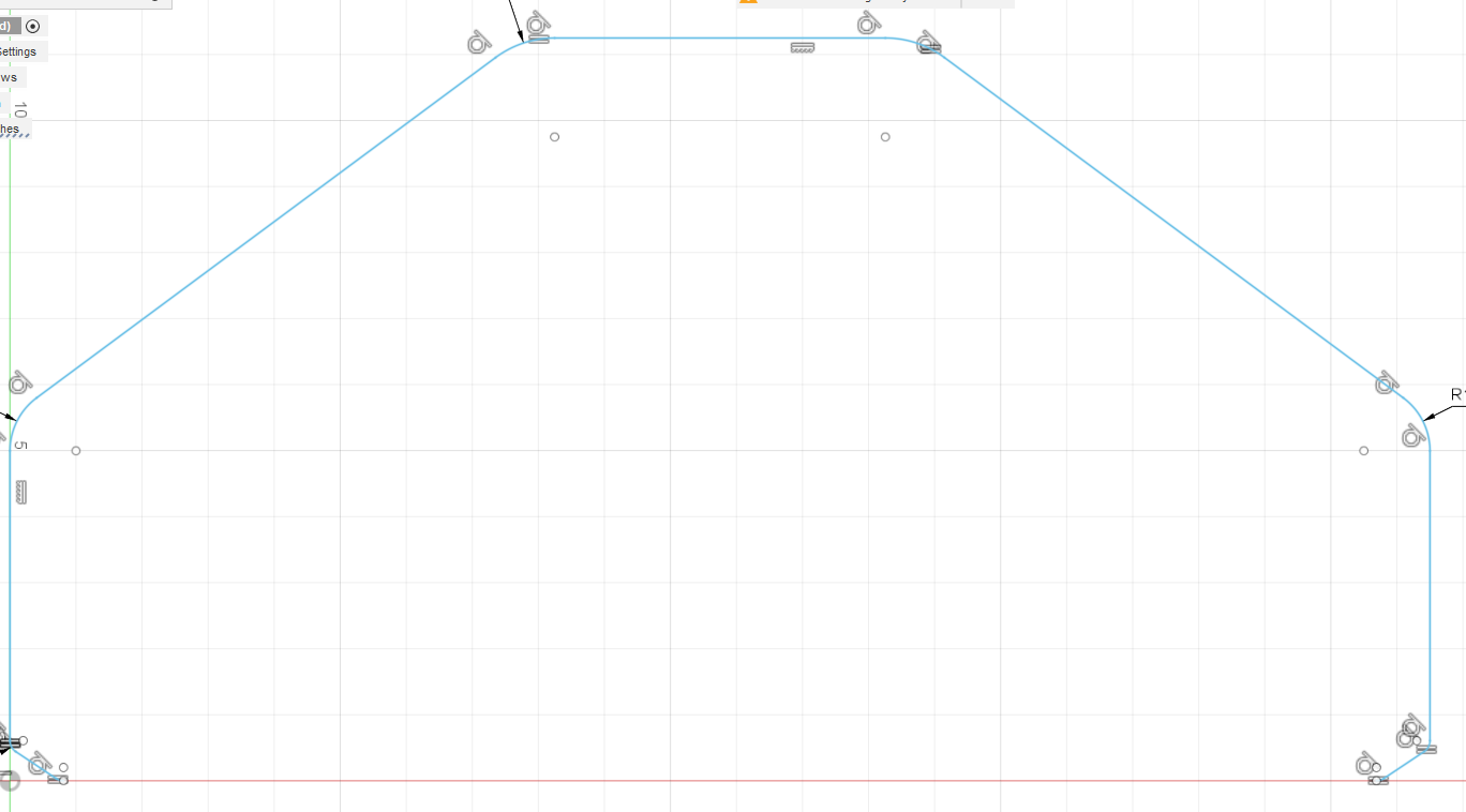
I have a question about how to make the G code file in fusion to cut a part that’s not a complete part in the designing feature. Hopefully this pic uploads showing what i need to cut out. It’s open across the bottom of the part. I have an engine plate that’s pre cut out for a SBC that i need to cut around the outer 2 sides and across the top but don’t know how to make it 1 solid line and save it in G code to cut it.
I think what you are asking is that you want to cut and “open contour”. It really is pretty easy:
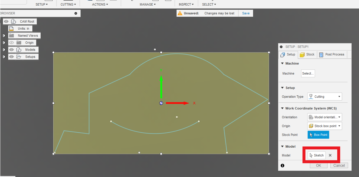
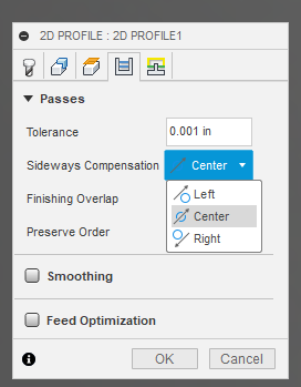
You go into manufacturing, do the setup and tell it you are using the “sketch”, and then when the tool path, same thing but make sure you pick “center compensation” and no lead-in, no lead-out.
I will edit this to show in images or send you to another post where I show it.
To complete the sketch selection, you will need to find the sketch in the browser tree and click on it. You can click on the line separate but picking the sketch is very easy and complete.
Now moving to the fourth tab:
On the fifth tab: NO lead-in, No lead-out and no pierce clearance.
Thanks Jim, one other question. When I’m in the manufacture process and have to pick the paths for it to follow is there a way to make it all one path. Right now i have to select a bunch of “pieces” that make up the line i want it to follow. Is there a way to get it to see only one complete line to follow? I tried to extrude but it wouldn’t give me that option.
That is why I was saying “if you can pick the entire sketch” Fusion will do a pretty good job of picking each segment in succession. You can pick them manually, but it is very, very tedious. You have to zoom up on it and try not to miss any tiny segment. You can press “CTRL” and left click and delete a segment without starting over. I think that is the command…but not entirely sure.
Another thing to make sure is that all of the segments of a group making up a single line have the arrows all pointing the same direction or flow. Otherwise, during the CAM process, Fusion will think you want it cut in separate sections. For those that have the arrow reversing the direction, hover over the red arrow and when it changes from red to pink, click on it. That will change the direction. If all the arrows line up right, even if they are picked in different orders, Fusion will CAM it the right way and connect them all.
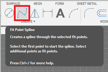
Yes. Understood. The best thing you can do to try to minimize your selections is to use the spline tool for large sections.
But even that gets kind of squirrel-y when you want a perfectly flat section or a perfectly, symmetrical curved area. When you finish a spline, that entire section is then one click for selection in the tool path.
Hello Guys, I too am having the same problem, Aksell has been looking at my F3 file trying to figure out what I have done to make my sketches all segments, i have zoomed way in to be sure there are no breaks in the lines, I have made three designs that just won’t get past making a program all around the part??
I tried double clicking on the periphery, no change?
Thanks for the help
Someone would be happy to look at it. Sometimes, I cannot even see why Fusion is thinking the segments are not selected. Some common issues:
There is another segment right on top of the line.
Sometimes, just deleting a line and redrawing it will bring the whole drawing to life.
Sometimes it is a line that extends ever so slightly past the point. That can be at an angle but it can also happen on a straight section.
I was working on one image and there appeared to be multiple ‘problem’ areas. For whatever reason, I just clicked on a line and deleted it and the entire image came to life. That was likely due to the image being mirrored so the other side of the entire image had the flaw repeated.
Wow!, TinWhisperer You are awesome! I can tell you are very comfortable working on computers. What you just did for me is like a miracle, because I am so out of my comfort zone. Thank you very much!