Fusion 360 "2D profile- cutting" operation questions

so, a few questions for those that have experimented or know better than i about the choices when setting a CAM 2D cutting profile, especially on thicker metals where the settings seem way more critical to getting a nice square cut. the first 3 tabs in the pop-up menu i think i got a good understanding of, they being Tool, Geometry and Heights… its the next couple that i have questions about.

  1. in the Passes tab:
    a) what do you set the “tolerance” at, and how does changing this affect the cut?
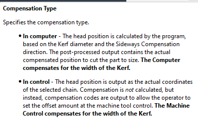
    b)does setting the “Compensation Type” affect cuts
    c) how much “Finishing Overlap” do you set? if you are cutting smaller bolt holes, is there a sweet spot to get the most circular hole possible?
    d) what do you set the “Outer Corner Mode” to?
    e) do you select “Smoothing Tolerance” and if so, what measurement to you enter?
    f) does selecting “Feed Optimization” make for better cuts, does it affect bolt holes, if you select it, what settings do you enter or how do you calculate what settings to enter?

2)in the “Linking” tab:
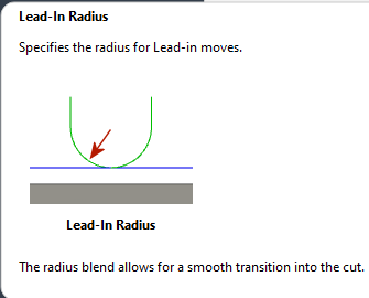
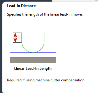
a)what “lead in radius” measurement do you enter?
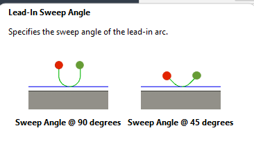
b)what “lead in sweep angle” works best
c)what “pierce clearance” do you set it at for the Razorweld 45?
d) what do you set the “lead out” and “same as lead in”?

thank you to all.

a. Tolerance: if you have a high tolerance, like the default of 0.0004, you might find that Fusion 360 is too finicky about picking the small contours. 0.004 is completely adequate.

b1. Sideways Compensation: Left is usually what we pick based on the right side of the cut being the better/finished side: thus, you want the cut to occur on the left side of the line. Center is used with single line, open contours such as a relief cut and so single line text.
b2. Compensation: Always “in computer”
image

c. Finishing overlap. Usually really small like 0.01 inches. Especially good to use if your are not using a lead-out. If you are using a lead-out, not as necessary to have a finishing overlap. If you see a little ‘nipple’ being left at the end of the cut, the finishing overlap may resolve it for you.

d. Outer corner mode: I have not used this but if you look at the options they help you make the corner more or less precise. Just the basic corner will have a slightly rounded look.

e. Smoothing tolerance: 0.01 to 0.004 would be reasonable but you might lose some detail in small areas. Experiment with it and look at how it changes your simulation in those areas.

f. Feed Optimization: This is where you tell the g-code to slow down your “cut speed” when encountering curves/circles where the radius is less than a stated amount. Usually set at 60% of your cut speed. This gives time for the plasma stream to catch up to the torch to fully cut the perpendicular cut that is desired. Note: this slow down will cause increased dross on the bottom of the plate by nature but is desired more than getting a sloped cut.

Linking tab:
a. lead-in radius: I use 0.03 to 0.1 based on the size of the contour I am trying to get
image

b. lead-in sweep angle: I usually pick 160 degrees
image

b2. Lead-in distance: I usually put: 0
image

c. Pierce clearance: not needed ever: 0
d. You will get lots of opinion. If you don’t use a lead out, make sure to put a finishing overlap. I rarely use the lead-out and have not noticed much of any issue.

Edit: Keep in mind, everyone has a different opinion and results with their particular set-up. I should have prefaced my remarks based on “this is what I do” and NOT “this is what should be done.” You will just need to do some trial and error research. Keep good notes and try not to vary too many things or you will not know what is causing what. And, pay attention to the consumables: that changes everything.

2 Likes

thank you very much, and yes keeping the plasma tips replaced regularly is a must when experimenting with changing parameters- something i learned the hard way.

I don’t think I really dove into your “making better holes” question.

That is what many of the settings, I shared, are geared toward.

  1. Finishing overlap could help but it is primarily the Feed Optimization that will help. But as I already mentioned, you will have more dross on the bottom side.

  2. The Sweep angle of 160 degrees and a very small lead in radius is what really makes for the nice cutting hole. By adjusting the lead in radius, you will be able to get it to the point that the lead-in is starting in the middle of the hole and sweeps outward until it finally is cutting the actual hole.

  3. Another thing you might think about is having several toolpaths: one for holes, one for relief cuts and open contours and one for the regular cuts. This is what you will eventually get to and why many people don’t want to give you settings for one path and have you think that is the entire answer/solution. In the above illustration you will see that I have one toolpath cutting the circles and a different one cutting the rest of the project as there are clearly different lead-ins being used. This was done with three different toolpaths.

  4. When the holes are too small for a lead-in of any kind, there are various ways to just peck in the center of the hole and then you will drill it out after your piece is cut. There has been various articles on this forum: search for “pecking center of holes.”

  5. In most all cases when you are planning to use the hole as is without lots of fuss, you will need to draft the hole with an extra 0.03 or 0.04 inches. A quarter inch hole would be 0.285 perhaps.

3 Likes