There were tons of topics related to DXF import and SVG import on INKSCAPE and many other SVG editor software type including adobe, Corel draw etc…
I took a few of the Forum FUSION design groups idea of how to improve svg and DXF file imports into fusion and tried them.
The first and foremost one that seems to have solved the Problem of not having complete geometry to select was from saving the file from Inkscape.
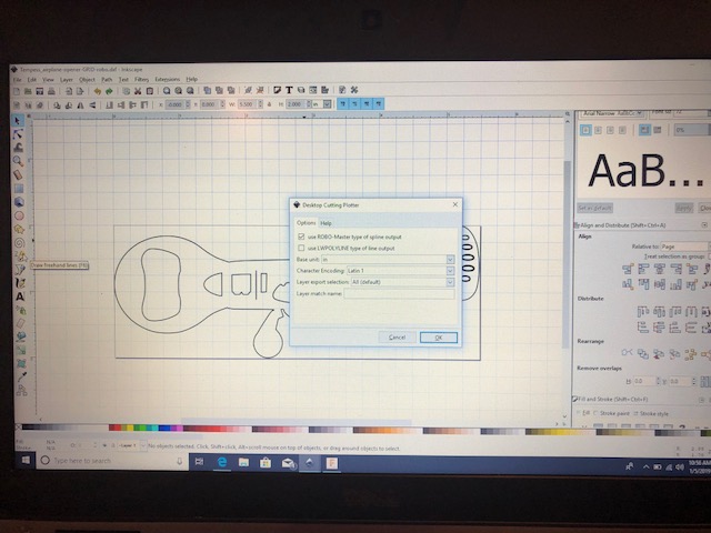
When saving the DXF you presented with the following:
![]() use ROBO-Master type of spline output
use ROBO-Master type of spline output
Use LWPOLYLINE type of line output
Default seems to be the LWPOLYLINE option.
I unchecked this and selected use ROBO- Master type spline output
From all my research it’s seems FUSION needs the spline type ROBO output
Otherwise it creates multiple geometries around your sketchlines trying to assemble a com0lete geometry to match your import shapes. This results in the Bazillions lines of geometry you have select when toolpathing.
Also be sure your scale is in inches which is the next selection.
Also in INSCAPE WHEN YOU SET Your new document up
I now select file.
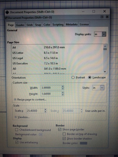
Document properties
Select all display units to inches
Orientation to landscape & units set to inches
Resize page to drawing selection
Scale is next and left at : scale X 25.4 user units per inch
Back round and border left as is
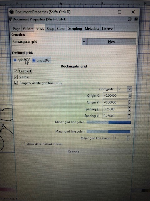
NEXT SELECTED - GRIDS
ONCE IN GRIDS you select NEW
Then I made sure that:
ENABLED
VISIBLE
Snap to visible grid lines only
Were all checked
Under Grid units set it in inches
Then I made sure that spacing X & spacing Y are set to 0.250” inches
ORIGIN X AND ORIGIN Y ARE set or left at -0.0000
Last that the Major grid line every: is set to 1
Show dots instead of lines is unchecked
Hit X your done
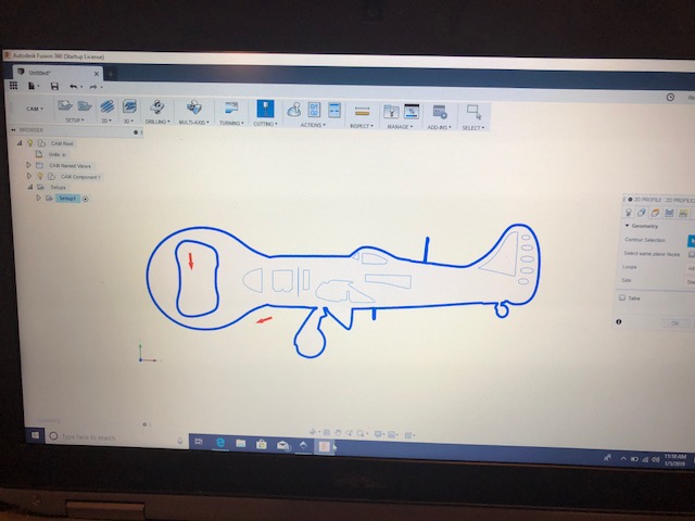
When I import the files now in DXF
THEY IMPORT IN THE EXACT DIMENSION I designed them in , in INKSCAPE
and the Coordinate is set exactly in the right spot on the plane face I selected in FUSION.
WHEN programming the toolpaths now so far selecting the geometries is one complete path now and not 30-40-50 chains for one 2” circle ,!!!,
So for now I’ve tried it 4 times on four different INKSCAPE DESIGNS
And so far so good.