HI guys, I am trying to learn how to cut out some stuff and would like to know how to force the machine to cut lines that are smaller than the kerf. For example, I made something with the text RIM ROCK in it. it won’t cut the small part of the letter M, the two tips of the letter C and the upper right corner of the letter K. However if it would simply try to cut them, it would look better if it didn’t cut them at all. I also tried this in the V8 emblem I downloaded from the fireshare site, and it wouldn’t tool path the triangular shapes in the 8.
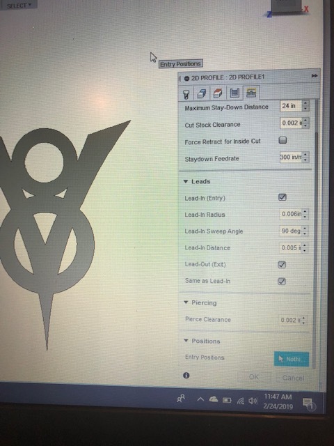
not exactly sure what you mean… if an area is to small for the torch to make the cut FUSION (if that’s what your using?) wont tool path it. you need to either adjust your set-up ex. lead-in, lead-out, pierce clearance. lead-in radius etc… so it would fit in those areas… I have been using a .6mm nozzle due to the smaller kerf you achieve for the finer detail stuff. they wear out alitte faster at the higher amperages but its a not a dealer breaker for me.
thickest stuff I need to cut so far is .105" and I get through it fine between 28-35 AMPS.
for cutting lines without closed geometry I change the set-up to center, and all the leadin ,out piecre clearance etc all on 0… this way the cut starts and finishes right on the line. just watch the time on the pierce delay. don’t set it to long or it will sit in that spot and cause burn out before it starts to move.
without more detail of your design ie. text size/stroke size , height.etc. its hard to ascertain what might be your issue. also what dimensions are you using? ie. what is the size of the project your trying to cut? what thickness material are you using and what is your torch set-up. ie. nozzle size
1 Like
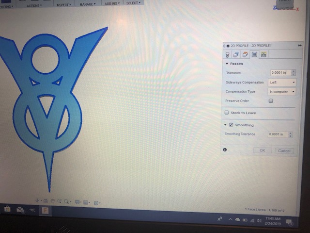
To achieve what I believe you are asking, lower the piece clearance number in CAM at the last tab of the “cutting” setup. It will trick the program into thinking it can fit and will cut it the best it can. Obviously it will not be exactly to size.
1 Like
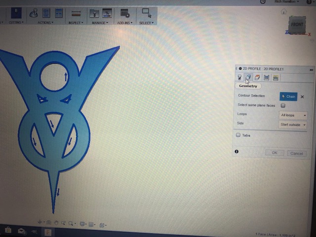
I just upload the ford v8 from fire share to try
all my settings are below and at first the two ttriangles were not tool pathed due to constraints
I just edited the settings a bit to allow the cuter to be able to moved within this area and everything tool pathed and simulated fine
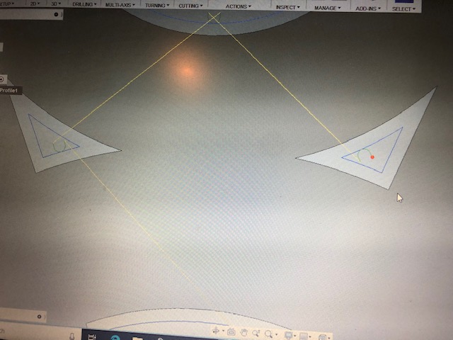
Thanks guys, I messed with it for several hours before I learned how to get around it. I also never knew i could do several tool paths on the same part. I ended up cutting the little triangles with a kerf that was way smaller than reality, and then a second tool path to cut the rest. Turned out pretty good actually
1 Like
That’s a good way if you have a bunch of small profiles. The other way to do this would be just to increase the size of the two triangles so one tool path would cut the entire part. Either way the triangles will end up being cut bigger then the drawn dimensions. Either way works.