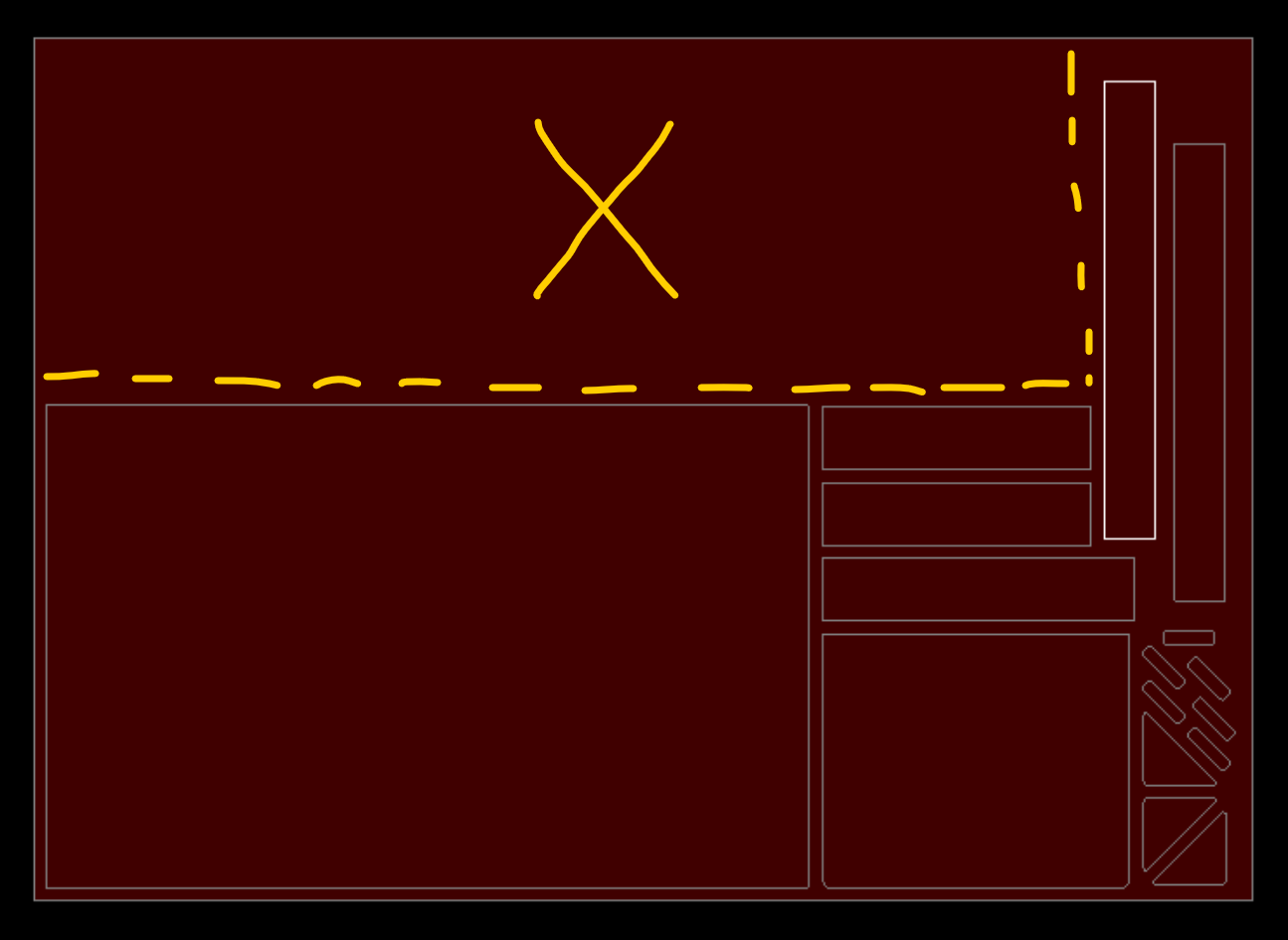
So, I have a 34x48 sheet of 10 gauge I’m cutting, and as you see in the picture below, the yellow
area with the X is excess material.
My question is; Is there a way to mark a line on the project (the yellow dashes) for the plasma cutter to cut so it will cut the excess off from the skeleton so I don’t have to go back and do it manually?
Preferrably, I’d like for it to do it as a final cut when the project finishes so I can take the excess and put it back in to my stock instead of going in and manually cutting it afterwards.
Note: I don’t know enough (correction: I don’t know anything) about gcode to write it myself. And with my workload, I don’t have much time to sit down and study it and practice to do it. As much as I would love to, it’s just not feasible at this time.
Thanks for any and all help in advance. It’s very appreciated!
Well, statistically speaking, I am one of those “other people” now. haha
I came across a feature I’ve never seen before and decided to explore it on some spare time.
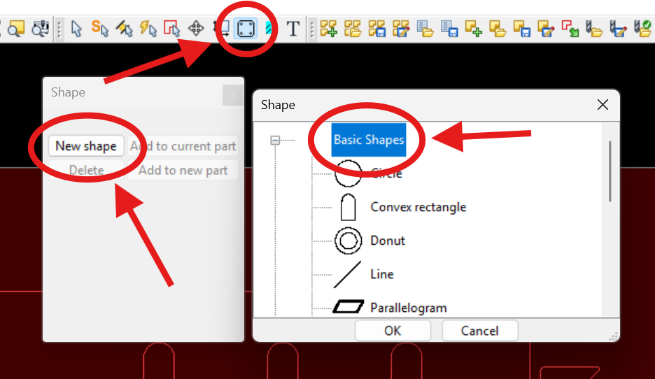
Looks like I can build a “cut off” in SheetCam by adding a few shapes/lines.
Had I seen this thread at the beginning, I would’ve suggested a basic rectangular drawing in DXF, then adding it to the project so it cuts that out as another item in your project.
I don’t use or own Sheetcam, but one member told me that you can save ‘projects’ so you can add additional items to cut on an existing skeleton that’s on your table. Always thought that was cool.
Yeah, that was one route we had considered taking, too.
We create everything in SolidWorks, so I’d have to customize a “part” to match what I needed to cut off everytime. Realized that was going to take too long, which is why we ruled out that option.
But, this quick shape option is a HUGE time saver for us!
And yeah, we’re still learning SheetCam when we have the time. We have the basics to get us by, but that’s it. haha
I’ve never used it for that, but the shape library is a quick way to make tabs, base plates, brackets, etc. Just put in the dimensions to create your part. No CAD program needed.
A sheetcam Part typically has a 1:1 relationship with a dxf. Import into an existing Part, and the former dxf for it is over written. Sheetcam TNG Development v7.1.35 (and 40) has a Part Combining feature, but that gets complicated when like named Operations and perhaps Layers occur.
A Part can be saved as a .part file rather than a job file. The difference is that a .part is just the bounds of the part, not the material size and other job settings. I have not found a good use case for .part.
.template is the opposite, it has job settings, including a toolset, but not the parts. I believe .template also has Operations but not Layers. My use case for .template is to reset my job settings (Options / ‘Job options’) when another job leaves it with more than obvious changes such as material size. I tried using it also for what I thought would be standard Operations but is anything really ‘standard’ with plasma process ?
I’m not aware that the Mode / ‘Shapes cutting lib’ is extendable by the user. There is a default.shapes file in the settings folder, but I found it only useful for custom rotary shapes or i-beams.
Would we be able to add custom “shapes” to the Shapes library? I see they have gussets in there, so we were thinking that maybe we can add our own commonly plasma cut gussets to the shapes library to quickly recall them instead of going through a multitude of files to find the gussets we use.
If we created the shapes to match the same parameters as needed by SheetCam to recall, would it be possible?
If so, do we need to name the file extension to something specific? Or is it more like a .dxf/.part/etc file that we can drop in the file folder?
see the same post above for info re. .part files, however .part files do not have parameters like the Mode / ‘Shapes cutting lib’. You can however scale a Part, right click the name, select Scale.