That’s good but if you would use a 1.1mm/60amp tip it may work even better.
2 Likes
I’ll give that a try. Thanks
Wolman, i have a IPTM60 machine torch im not using if you want it you can pay shipping and you can have it. i tried selling it on ebay and got no hits. have a pile of new consumables as well.
i was using it on a 40 amp chinese plasma cutter and even at 40 amps it didnt want to cut well . was even worse at 20 amps. i think they are meant to run at 60 or higher amps and not less.
2 Likes
As a question on everlast 82 i what service amps are you running (service pannel amp breaker)
I am running an 80 amp breaker. Sometimes I run a 102i so I ran it accordingly. It is important to ensure that your wire is rated for the amperage you decide on. A 50 amp breaker would suffice.
2 Likes
Well thats what everlast said but atempted to cut 1 inch thick material ,blew the breaker 3 times, and real messed up the program , orderd match amp breaker 80 amps .wired just the plasma cutter for 100 aamps a long time ago
1 Like
Its not just the breaker you also need to use the right size wire to handle the amps. A 50 amp breaker needs #6 wire a 100 amp needs #2 wire depending on code. Yes I know you can get by with lesser gauge to welders and plasma cutters but I always took the high road.
4 Likes
Remember the breaker is sized to the wire it’s there to protect.
Everlast’s Manual is very clear on the approach for sizing the breaker and wire.
here it the excerpt from the Everlast manual
" Breaker Sizing and Wiring Requirements
Before installation of this unit in any facility, always consult a licensed local electrician familiar with the requirements of properly wiring a plasma cutter
into the electrical supply. Refer to the National Electric Code (NEC) and local codes. If needed, refer the electrician to Article 630 of the NEC during
consultation to determine proper application and wiring needs. Use the I1MAX and the I1EFF ratings listed above to determine the proper breaker and
conductor (wire) sizing required. Everlast plasma cutters are designed around use in industrial wiring applications and are intended to be used with
modern electrical systems. Household wiring may need to be upgraded before this plasma cutter may be installed. Additional HF protection and isolation may be needed if this plasma cutter interferes with the operation of electrical/electronic equipment.
IMPORTANT: Do not modify plasma cutter wiring. This unit meets the standards for conductor sizing on the power cable and takes into account power
cable length, duty cycle and rated current. "
Input rating from the manual
"Maximum Inrush Amps (I1MAX) 55A A @ 240V 1 Phase
Maximum Rated Effective Amps (I1EFF) 43A"
This article for size is cited in Everlast manual
" 630.1 Scope
This article covers apparatus for electric arc welding, resistance welding, plasma cutting, and other similar welding and cutting process equipment that is connected to an electrical supply system.
630.6 Listing
All welding and cutting power equipment under the scope of this article shall be listed.
630.8 Ground-Fault Circuit-Interrupter Protection for Personnel
All 125-volt, 15- and 20-ampere receptacles for electrical hand tools or portable lighting equipment, supplied by single-phase branch circuits rated 150 volts or less to ground, installed in work areas where welders are operated shall have ground-fault circuit-interrupter protection for personnel.
630.11 Ampacity of Supply Conductors
The ampacity of conductors for arc welders shall be in accordance with 630.11(A) and (B).
(A) Individual Welders
The ampacity of the supply conductors shall be not less than the I 1eff value on the rating plate. Alternatively, if the I 1eff is not given, the ampacity of the supply conductors shall not be less than the current value determined by multiplying the rated primary current in amperes given on the welder rating plate by the factor shown in Table 630.11 (A) based on the duty cycle of the welder.
(B) Group of Welders
Minimum conductor ampacity shall be based on the individual currents determined in 630.11(A) as the sum of 100 percent of the two largest welders, plus 85 percent of the third largest welder, plus 70 percent of the fourth largest welder, plus 60 percent of all remaining welders.
Exception: Percentage values lower than those given in 630.11(B) shall be permitted in cases where the work is such that a high-operating duty cycle for individual welders is impossible.
Informational Note: Duty cycle considers welder loading based on the use to be made of each welder and the number of welders supplied by the conductors that will be in use at the same time. The load value used for each welder considers both the magnitude and the duration of the load while the welder is in use.
Table 630.11 (A) Duty Cycle Multiplication Factors for Arc Welders
Duty Cycle Multiplier for Arc Welders
Nonmotor Generator Motor Generator
100 1.00 1.00
90 0.95 0.96
80 0.89 0.91
70 0.84 0.86
60 0.78 0.81
50 0.71 0.75
40 0.63 0.69
30 0.55 0.62
20 or less 0.45 0.55
630.12 Overcurrent Protection
Overcurrent protection for arc welders shall be as provided in 630.12(A) and (B). Where the values as determined by this section do not correspond to the standard ampere ratings provided in 240.6 or where the rating or setting specified results in unnecessary opening of the overcurrent device, the next higher standard rating or setting shall be permitted.
(A) For Welders
Each welder shall have overcurrent protection rated or set at not more than 200 percent of I 1max. Alternatively, if the I 1max is not given, the overcurrent protection shall be rated or set at not more than 200 percent of the rated primary current of the welder.
An overcurrent device shall not be required for a welder that has supply conductors protected by an overcurrent device rated or set at not more than 200 percent of I 1max or at the rated primary current of the welder.
If the supply conductors for a welder are protected by an overcurrent device rated or set at not more than 200 percent of I 1max or at the rated primary current of the welder, a separate overcurrent device shall not be required.
(B) For Conductors
Conductors that supply one or more welders shall be protected by an overcurrent device rated or set at not more than 200 percent of the conductor ampacity.
Informational Note: I 1max is the maximum value of the rated supply current at maximum rated output. I 1eff is the maximum value of the effective supply current, calculated from the rated supply current (I 1), the corresponding duty cycle (duty factor) (X), and the supply current at no-load (I o) by the following equation:
[630.12(B)]

630.13 Disconnecting Means
A disconnecting means shall be provided in the supply circuit for each arc welder that is not equipped with a disconnect mounted as an integral part of the welder.
The disconnecting means shall be a switch, circuit breaker, or listed cord-and-plug connector, and its rating shall be not less than that necessary to accommodate overcurrent protection as specified in 630.12.
630.14 Marking
A rating plate shall be provided for arc welders giving the following information:
- Name of manufacturer
- Frequency
- Number of phases
- Primary voltage
- I 1max and I 1eff, or rated primary current
- Maximum open-circuit voltage
- Rated secondary current
- Basis of rating, such as the duty cycle
630.15 Grounding of Welder Secondary Circuit
The secondary circuit conductors of an arc welder, consisting of the electrode conductor and the work conductor, shall not be considered as premises wiring for the purpose of applying Article 250.
Informational Note: Connecting welder secondary circuits to grounded objects can create parallel paths and can cause objectionable current over equipment grounding conductors.
630.31 Ampacity of Supply Conductors
The ampacity of the supply conductors for resistance welders shall be in accordance with 630.31(A) and (B).
Informational Note: The ampacity of the supply conductors for resistance welders necessary to limit the voltage drop to a value permissible for the satisfactory performance of the welder is usually greater than that required to prevent overheating.
(A) Individual Welders
The ampacity of conductors for individual welders shall comply with the following:
- The ampacity of the supply conductors for a welder that can be operated at different times at different values of primary current or duty cycle shall not be less than 70 percent of the rated primary current for seam and automatically fed welders, and 50 percent of the rated primary current for manually operated nonautomatic welders.
- The ampacity of the supply conductors for a welder wired for a specific operation for which the actual primary current and duty cycle are known and remain unchanged shall not be less than the product of the actual primary current and the multiplier specified in Table 630.31(A) for the duty cycle at which the welder will be operated.
(B) Groups of Welders
The ampacity of conductors that supply two or more welders shall not be less than the sum of the value obtained in accordance with 630.31 (A) for the largest welder supplied and 60 percent of the values obtained for all the other welders supplied.
Informational Note: Explanation of Terms
- The rated primary current is the rated kilovolt-amperes (kVA) multiplied by 1000 and divided by the rated primary voltage, using values given on the nameplate.
- The actual primary current is the current drawn from the supply circuit during each welder operation at the particular heat tap and control setting used
- The duty cycle is the percentage of the time during which the welder is loaded. For instance, a spot welder supplied by a 60-Hz system (216,000 cycles per hour) and making 400 15-cycle welds per hour would have a duty cycle of 2.8 percent (400 multiplied by 15, divided by 216,000, multiplied by 100). A seam welder operating 2 cycles “on” and 2 cycles “off” would have a duty cycle of 50 percent.
Table 630.31(A) Duty Cycle Multiplication Factors for Resistance Welders
| Duty Cycle (%) | Multiplier |
|---|---|
| 50 | 0.71 |
| 40 | 0.63 |
| 30 | 0.55 |
| 25 | 0.50 |
| 20 | 0.45 |
| 15 | 0.39 |
| 10 | 0.32 |
| 7.5 | 0.27 |
| 5 or less | 0.22 |
630.32 Overcurrent Protection
Overcurrent protection for resistance welders shall be as provided in 630.32(A) and (B). Where the values as determined by this section do not correspond with the standard ampere ratings provided in 240.6 or where the rating or setting specified results in unnecessary opening of the overcurrent device, a higher rating or setting that does not exceed the next higher standard ampere rating shall be permitted.
(A) For Welders
Each welder shall have an overcurrent device rated or set at not more than 300 percent of the rated primary current of the welder. If the supply conductors for a welder are protected by an overcurrent device rated or set at not more than 200 percent of the rated primary current of the welder, a separate overcurrent device shall not be required.
(B) For Conductors
Conductors that supply one or more welders shall be protected by an overcurrent device rated or set at not more than 300 percent of the conductor ampacity.
630.33 Disconnecting Means
A switch or circuit breaker shall be provided by which each resistance welder and its control equipment can be disconnected from the supply circuit. The ampere rating of this disconnecting means shall not be less than the supply conductor ampacity determined in accordance with 630.31. The supply circuit switch shall be permitted as the welder disconnecting means where the circuit supplies only one welder.
630.34 Marking
A nameplate shall be provided for each resistance welder, giving the following information:
- Name of manufacturer
- Frequency
- Primary voltage
- Rated kilovolt-amperes (kVA) at 50 percent duty cycle
- Maximum and minimum open-circuit secondary voltage
- Short-circuit secondary current at maximum secondary voltage
- Specified throat and gap setting
630.41 Conductors
Insulation of conductors intended for use in the secondary circuit of electric welders shall be flame retardant.
630.42 Installation
Cables shall be permitted to be installed in a dedicated cable tray as provided in 630.42(A), (B), and (C).
(A) Cable Support
The cable tray shall provide support at not greater than 150-mm (6-in.) intervals.
(B) Spread of Fire and Products of Combustion
The installation shall comply with 300.21.
(C) Signs
A permanent sign shall be attached to the cable tray at intervals not greater than 6.0 m (20 ft). The sign shall read as follows:
CABLE TRAY FOR WELDING CABLES ONLY"
so in this case that is
There is the information for the conductor size
Now the breaker (overcurrent protect device)
Looks like the very maximum breaker size is 200% of
2 Likes
I forget how I got to this thread, but with the conversation about service amperage and such has me chiming in.
Today I was running the 102i with a clamp on amp meter on the input power. The 102i spec sheet says 82 amps max inrush; my meter recorded as high as 112 amps going in the machine. Accuracy spec for the meter is 2.0% + 8D so it seems probable it was pulling 30%+ better than the specs say it can.
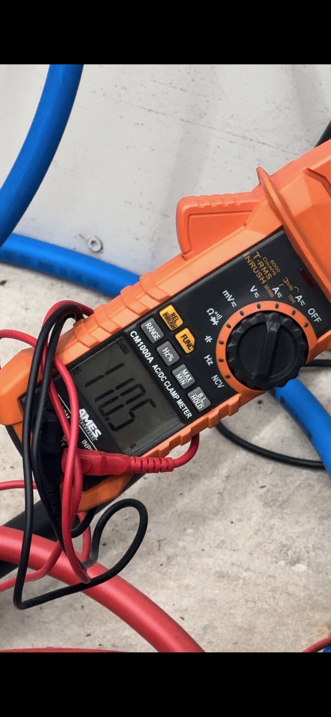
What is the voltage? Lower voltage will increase amp draw. You may have a long run from the panel and get a voltage drop under a load. Do the same test again, but measure the voltage and see if it is the same as when the cutter is off.
My 102i pulls 79 amps at 240 volts.
3 Likes
Unless I’m mistaken, Being nominally 36% over on amperage attributable to voltage drop would imply a running voltage of ~154v on the normal 240v circuit… I’m pretty sure the smoke from the wiring’s insulation would be a dead giveaway.
Still, I’m curious and will test it.
1 Like
You got this. My 102i pulls 79 amps inrush like I said, and it drops to about 55 amps at 100amps DC output. My shop is wired with almost no voltage drop on any of my machines. It could be a plasma problem.
7.4% voltage drop at most when pulling 110 amps from today’s test. There’s over 200’ of wire between the measuring point on the plasma and the service meter.
Peak numbers:
243V resting
224V at 110 amps
That is a lot of voltage drop. How often do you actually use 100 amps?
You could increase the size of the conductors.
Underground or aerial?
200’ you should run 4/0 aluminum for a 100 amp sub panel.
The bare minimum is 2/0 aluminum. I love over kill.
That would give you about a 3% voltage drop
The 2/0 would be around 230 volts @ 100amps
The 4/0 would be. around 236 volts @,100 amps
2 Likes
My point is the plasma shouldn’t be pulling 110 amps from the wall when its max inrush is listed at 82 amps and max rated is 64 amps.
7.5% voltage drop on a 50 amp circuit/60 amp breaker supplying 120% of its design capacity isn’t remarkable. That implies a 3.4% voltage drop at 50 amps.
1 Like
Obviously I don’t know your situation. Having the utility get you a transformer and give you a service drop.
You may have a plasma cutter problem. If you temp wire it in at the service panel, see what you get.
Dropping 19v will make the amps go up.
It would let you know if it’s the plasma cutter.
I checked mine this morning. 78.5 amps at 100 amps DC output. During the cut if fell to a out 55 amps.
1 Like
Give Everlast a call tomorrow. Their tech support is on eastern time.