When trying to create the cut paths the tolerance seem to be way too high and many get discarded. I’m following the tutorials, using the architectural plate and all the general settings recommended in the video. All the screw holes get skipped.
Only when I increase their diameter to at least 0.300 will they be cut. I’ve tried several of the projects from the site, and have a similar issue, any smaller geometry won’t get done. I’ve tried reducing all the dimensions in the tool library to see if maybe they were too big and it doesn’t seem to help.
I figured that much, only problem is I’m following your tutorial exactly. I’ve also started over several times and redid it from scratch just to be sure I wasn’t missing something. Your video only has us changing two settings when creating the tool function (Kerf and Diameter)
Is there some other setting that was just taken for granted and not shown?
Funny. Years later, here I am making the exact mistake. I just watched Daniel’s video. Had the problem with it skipping my .25 holes. Searched the subject error. Landed here. Fixed it… now lets go cut!! I am loving Fusion btw. I should have started here and skipped sheetcam.
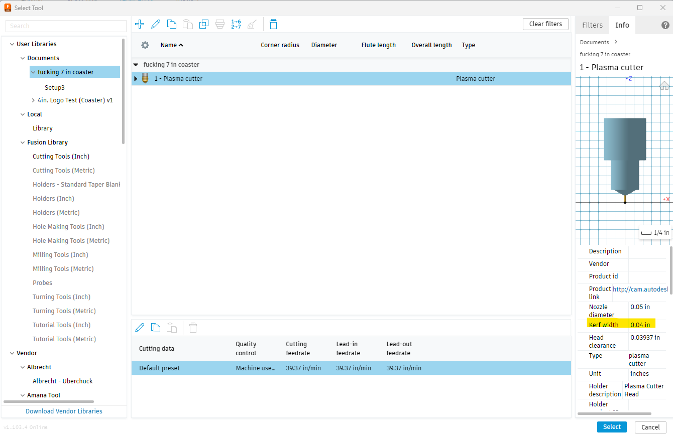
I am using default preset plasma cutter with 0.04 in kerf.
i was able to successfully cut a part provided via fireshare, but the part i am trying to cut now has a more organic shaped logo. i suspect at minimum the base file needs to be revised slighlty to eliminate the tiny radius that i am seeing at what should be a corner.
okay so i redrew the base file and am reading out a valid toolpath now.
I left the default settings on the “linking” portion and still reads out as valid. it seems rather odd that you have to change to the settings that danial advised every single time you create a toolpath tho.
i opted not to this time around and as mentioned, got a valid tool path.
edit: ahh i take it back. the organic shape that was problematic before works fine now, but now my lettering is having toolpaths discarded after scaling everything down to the intended size. I guess it is just a resolution limitation for how small of text/complicated the font is as the determining factor. (and this is after using the settings that daniel advised.)
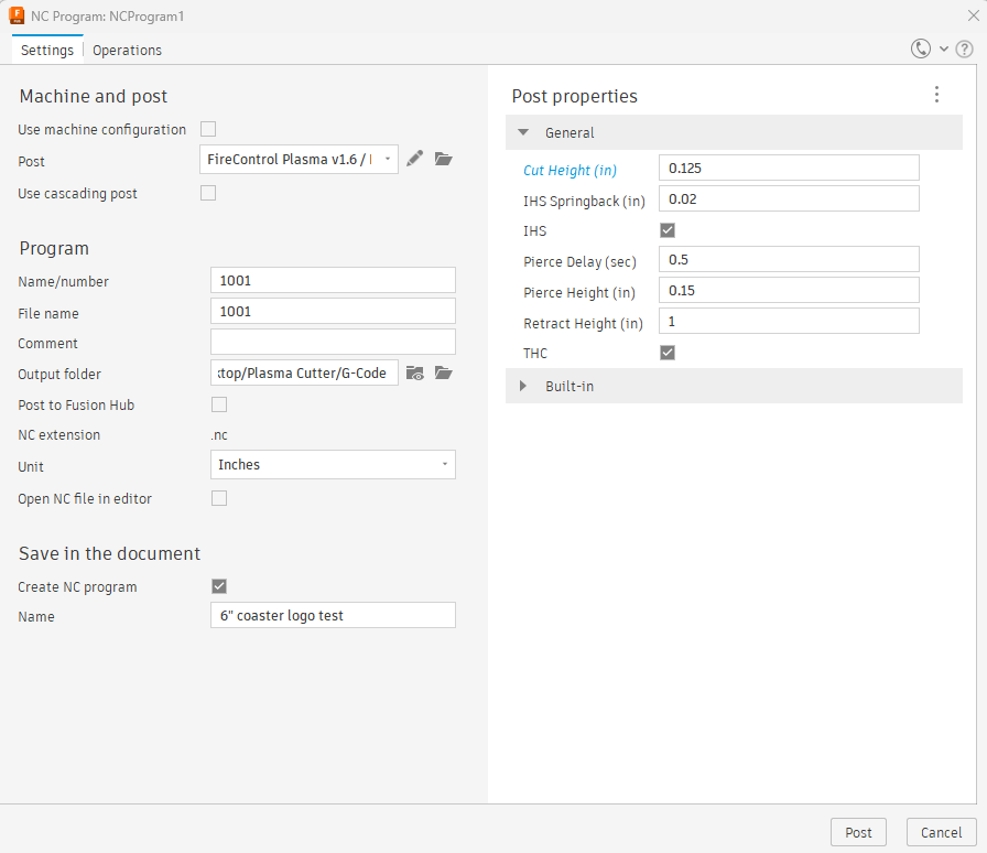
Thank you. Could you please help me understand the significance/impact of setting the cut height and subsequent information in Fusion once you press the Post-Process button and it launches the NC Program pop up window.
I have my THC set up, and toggled on already. I assume I as the operator am supposed to know the appropriate cut height and adjust accordingly depending on the base material that i am trying to cut? (similar to how there’s welding charts for what amperage to use for different material thicknesses?) This way i would set the height and the THC would work to preserve the subsequent voltage that is generated at the set height?
Or does the THC work to determine that information out by itself and it disregards the information determined in the photo above?
Hopefully that makes sense. Still learning over here.
edit: does cut height translate to the distance from the base material to the tip of the torch? or is cut height the depth of the material that i am trying to cut?
Notice that I said in this chart above in red “Data that may or may not pass thru.” With the post processor that it provided by the Langmuir website, these values DO NOT currently pass thru to that post processing page. That is why you need to enter them even though they are in your “tools.” The good news is that once you enter them on this post-processing page, they will re-populate with the last figures that were in those categories.
There is one thing to note, if you download and open someone else’s f3d file and go to the post processing page, those values will now be there. So write down your numbers on a card so you can verify the correct values are there.
In a way, yes. THC will monitor the voltage for the first 0.25 inches and that average voltage will be the target that THC uses.
Nothing is going to “set your voltage” in NOMINAL VOLTAGE, except FireControl may keep the nominal voltage setting from the last time you used it. You must always check to be sure it is the voltage you intended by looking at your notes or cut chart and you will set that voltage.
If THC is set to nominal voltage and you enter a voltage number, THC will disregard the information set for cut height and strive to meet the nominal voltage. FireControl will initially put the torch at the cut height you set but THC will take over and put the torch at the height that gives the voltage you set.
But if you are using “smart voltage” it follows the process of monitoring the first 0.25 inches of cutting described above.
Cut height is measured from the top surface of the material to the tip of the nozzle of the torch.
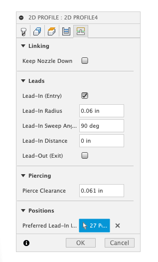
@TinWhisperer - is there a way to save the settings in 2D profile so you don’t have to re-enter them every single time? I keep getting different error messages and then I have to go back in an re-set every time. help lol
Thanks for the information in this thread (that I am now un-burying.) How small of lines/holes are “too small?” I am trying to cut out the “tattered flag” and I am struggling to get it to cut the lines (that make the stripes.) I don’t remember exactly, but I think I scaled it down some from the design I got. It is s roughly 18” x 24. I measured the lines/stripes and it looks like they are 0.069”. I thought it (software) would still try to cut it. Is that too small? (I have cut some pretty skinny lines before, so not sure that is it.)
I have tried all that was suggested here, and then some. Lead-in Radius from completely off, to 0.1-0.10. Lead in sweep angle from 30,40,50,60,70,90 degress. Sideways compensation from left to center.
If it is too small, I guess I can scale it up but thought I would see if you guys have any advice.
That is really small. Anything smaller than 0.11 inches is hit and miss at the plasma table, let alone being discarded by fusion. If you are using fine cut consumables you might get lucky.
Try creating another tool path and set lead in/out to 0.0 and no Pierce clearance. If that doesn’t take it then it is smaller than your kerf width.