Detailed home/limit switch installation

For reasons, I really wanted Home/Limit switches on the Crossfire. While the forum is full of tantalizing hints of people succeeding at this, I couldn’t find a soup to nuts explanation of how to go about it. After much testing and experimentation, I have them working on my Crossfire and wanted to share the info with interested others.

The good news is that the Mach3 controller board inside the Crossfire has 4 unused input pins. These pins can be used for any four things you, as a user, desire. For me, they are;

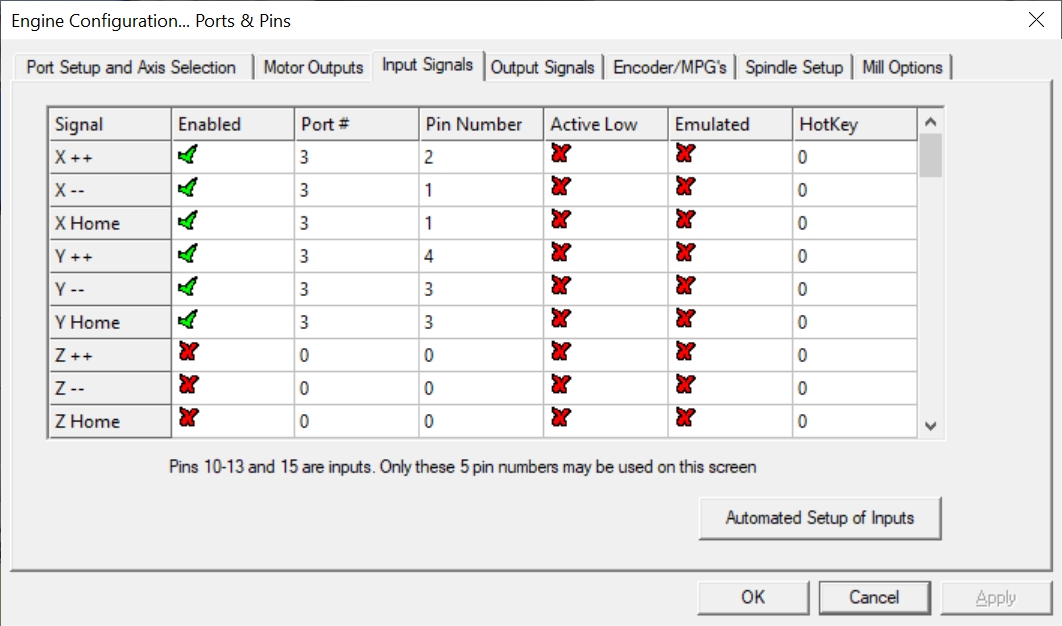
  1. Home-X/X-- Limit (dual duty)
  2. X++ Limit
  3. HOME-Y/Y–Limit (dual duty)
  4. Y++ Limit

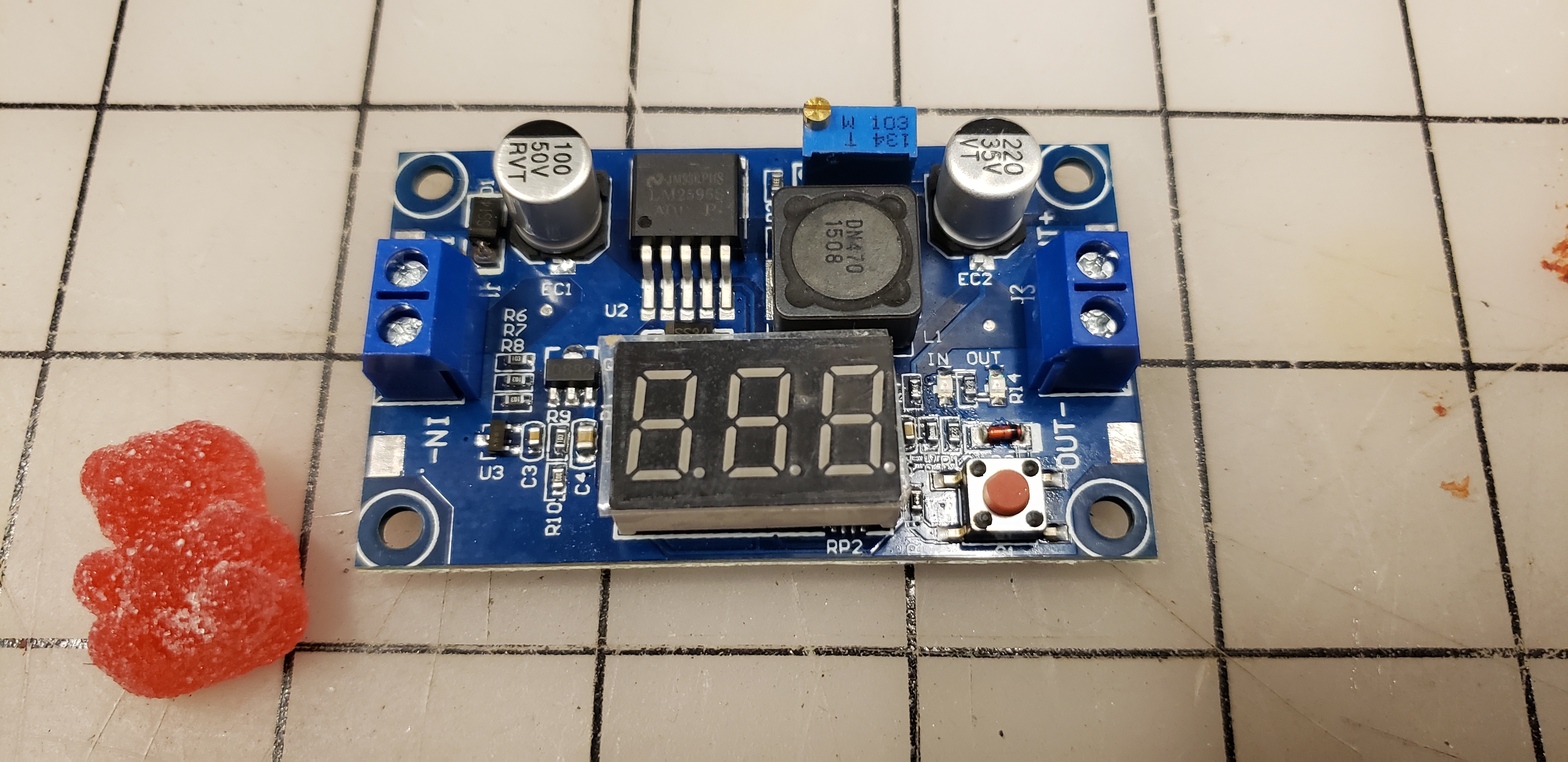
To utilize these inputs, the controller board requires 24VDC input. Other posters have noted that have succeeded with lower voltages, potentially even swapping a resistor on the controller to allow use of the USB provided 5VDC. I chose a different route and added a Buck Converter to step down the 36VDC provided by the Motor Power Supply to 24VDC. I used a programmable converter:
https://smile.amazon.com/gp/product/B07L915WKX/


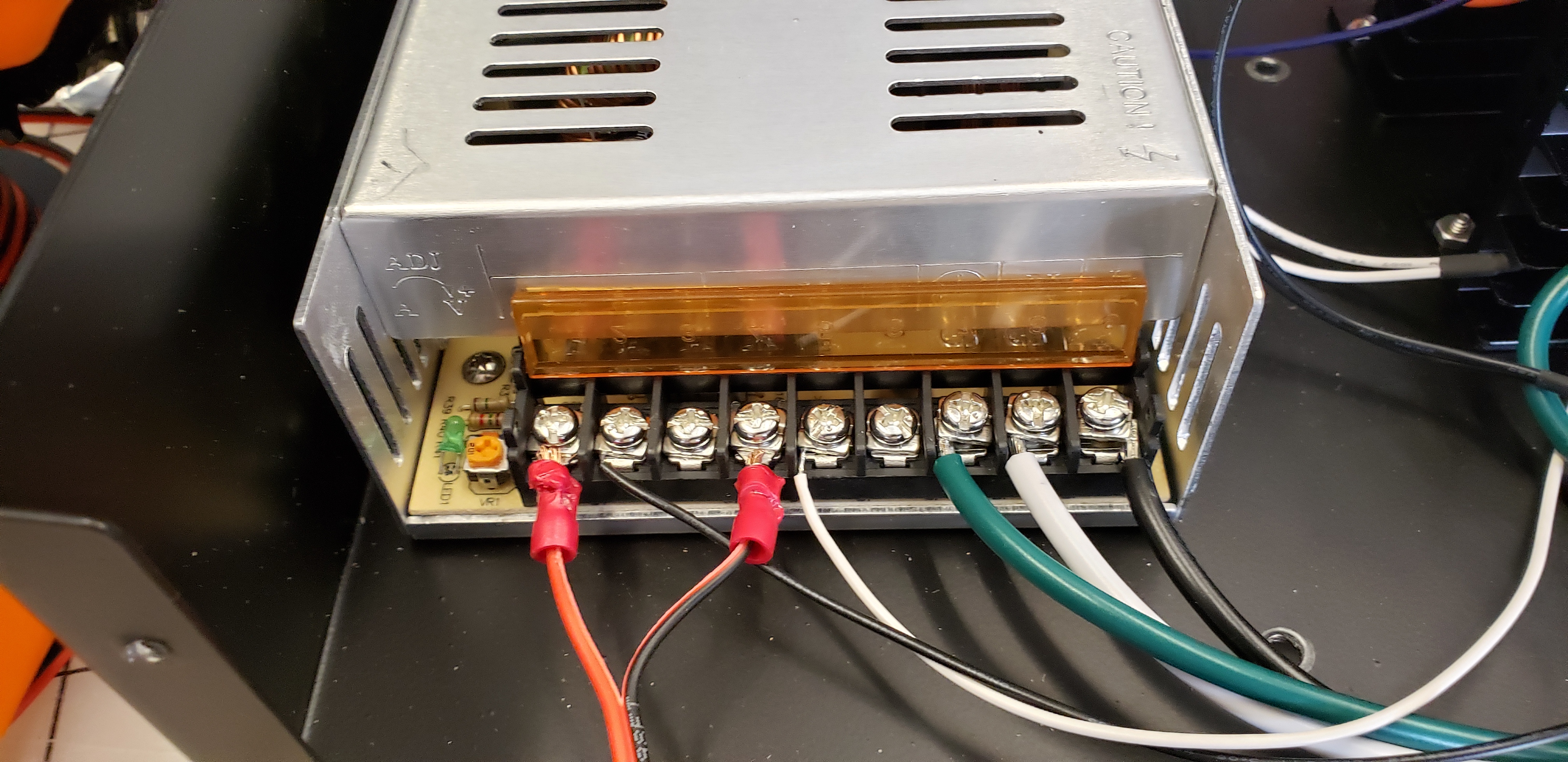
This took input from the V+ and V- outputs on the power supply:

I adjusted the output to 24V and mounted the converter using standoffs onto the Crossfire control panel:

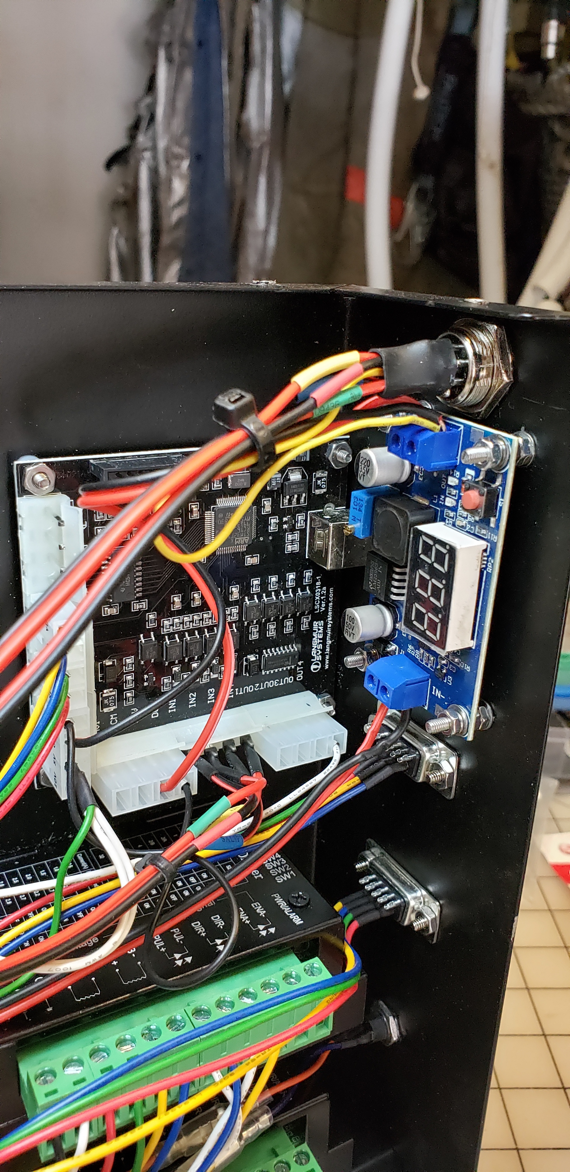
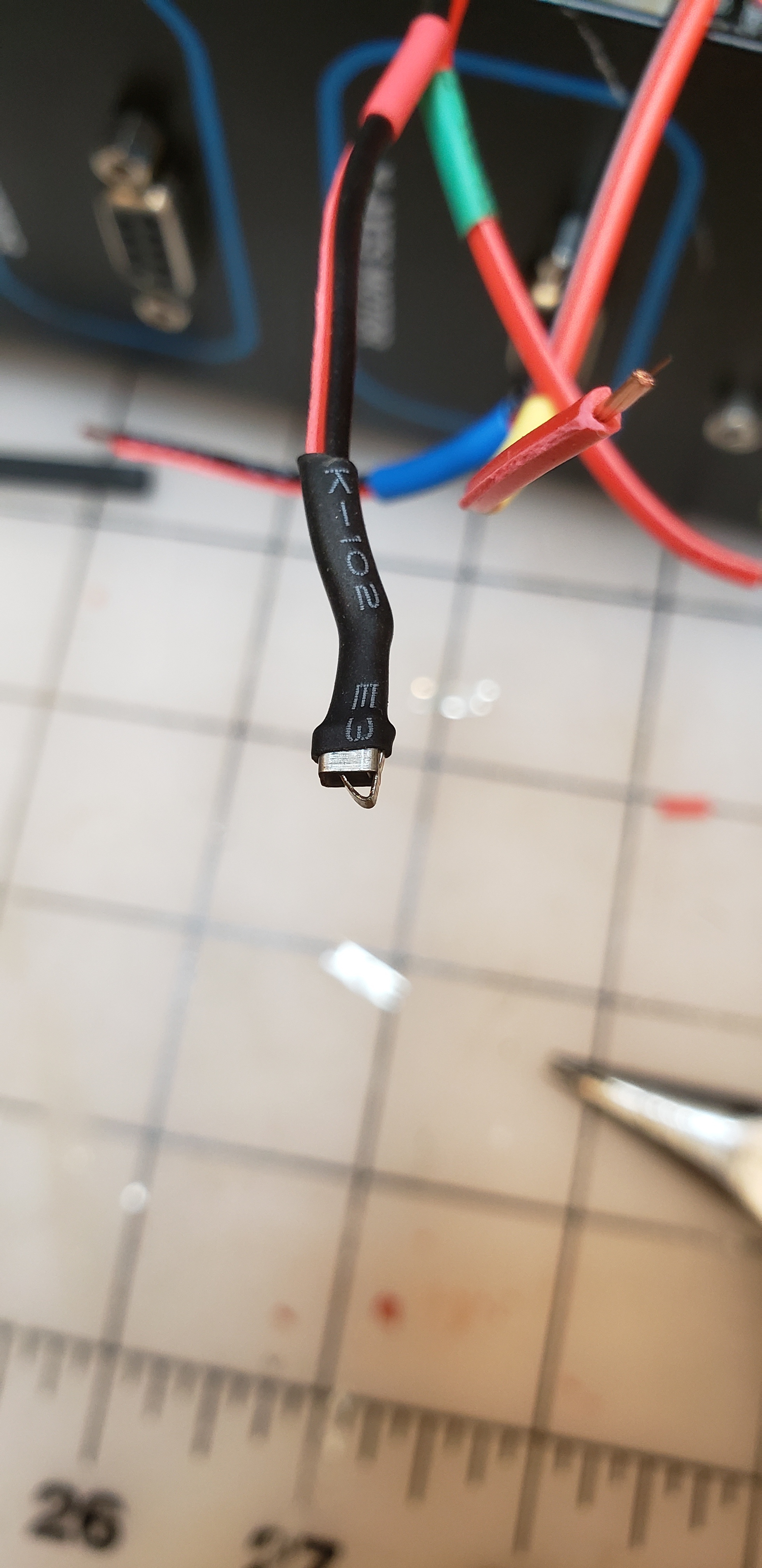
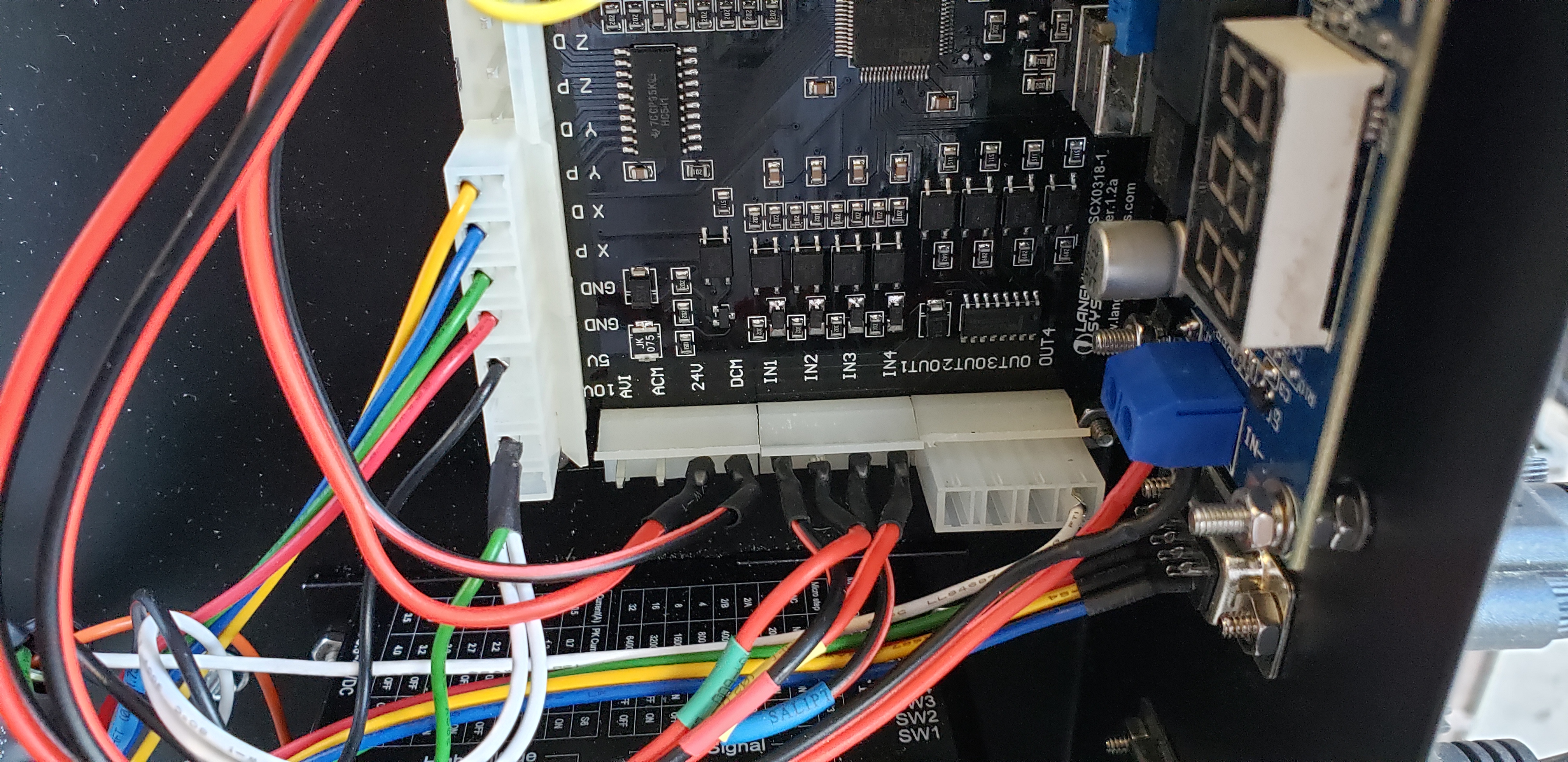
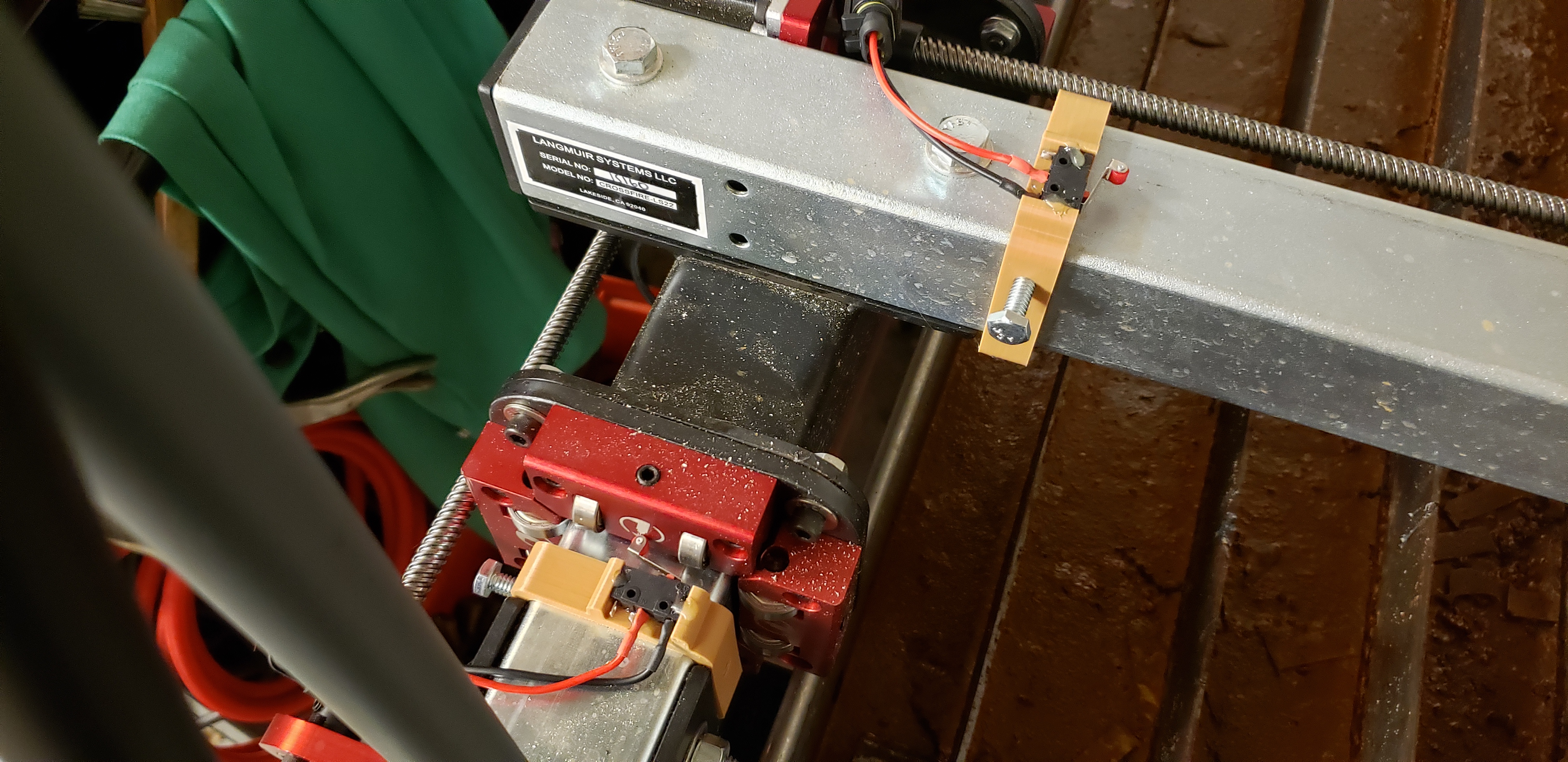
The positive output of the converter is sent to the 24V pin on the controller board and the negative output to the DCM pin. I removed the existing plug and connected directly to the board pins using crimped JST female connectors with heat shrink around them. JST connectors are technically too small, but with the heat shrink they’ll hold tight and they’re what I had in stock.


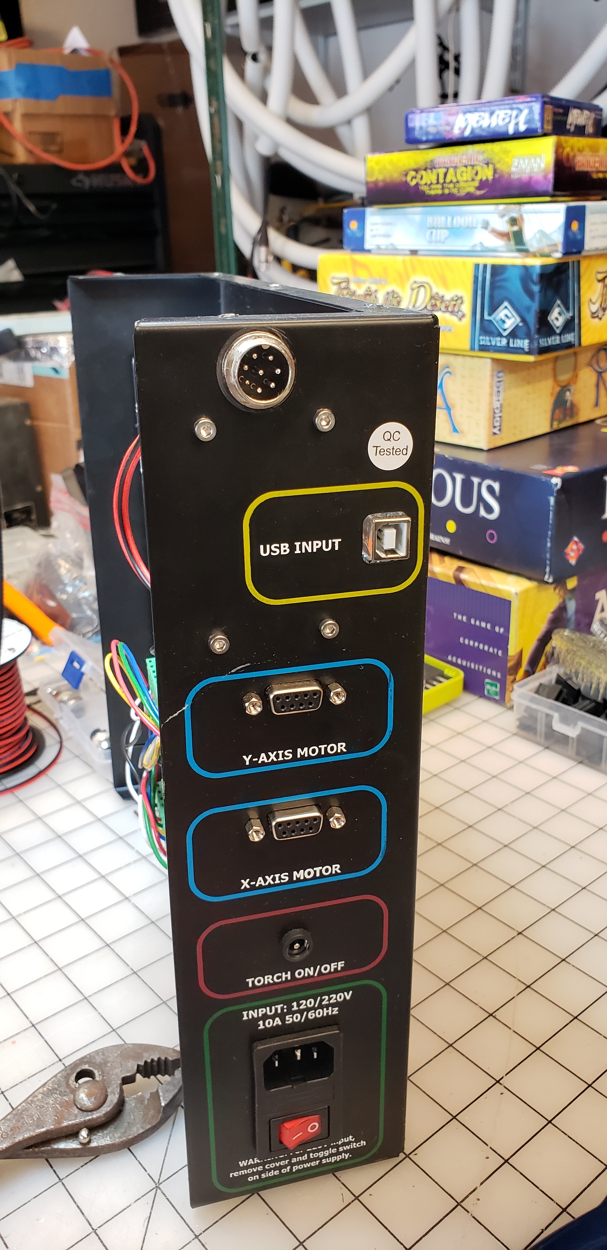
I mounted an 8pin aviation connector onto the panel for the limit switches to connect to.
https://smile.amazon.com/gp/product/B077485NWB/


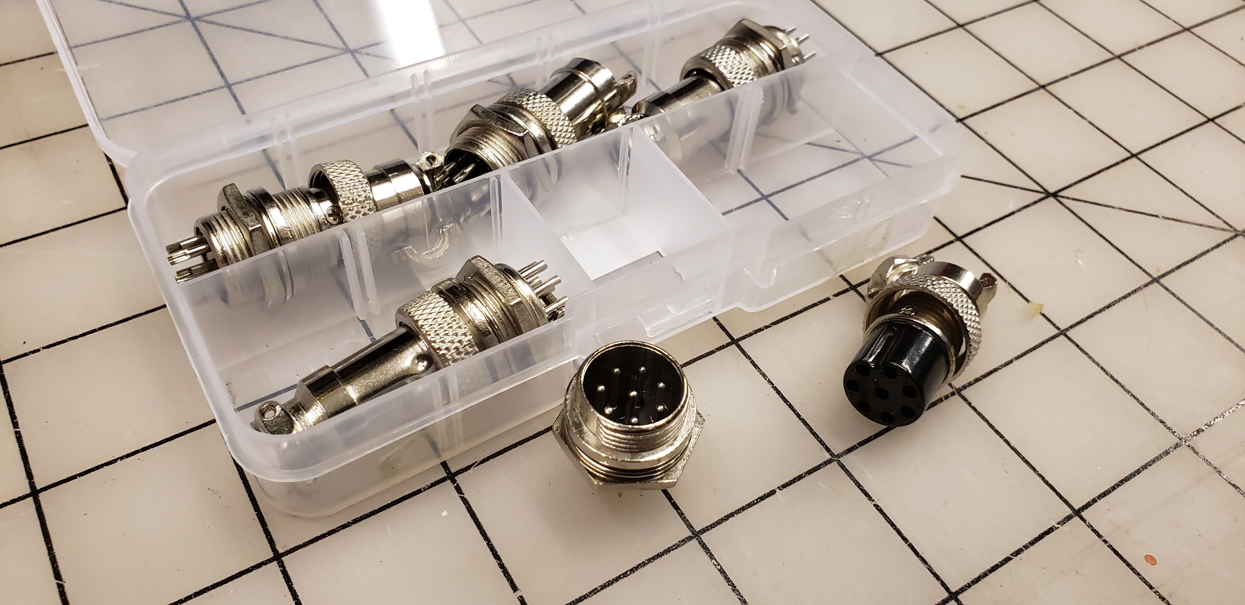
You have to share the 24V ground signal among the limit switches. I chose to do this inside the control panel so that there are 4 pairs of wires exiting the box. You could choose a different scheme and be just fine. I bridged the even number pins on the panel side mount of the connector to share the ground:

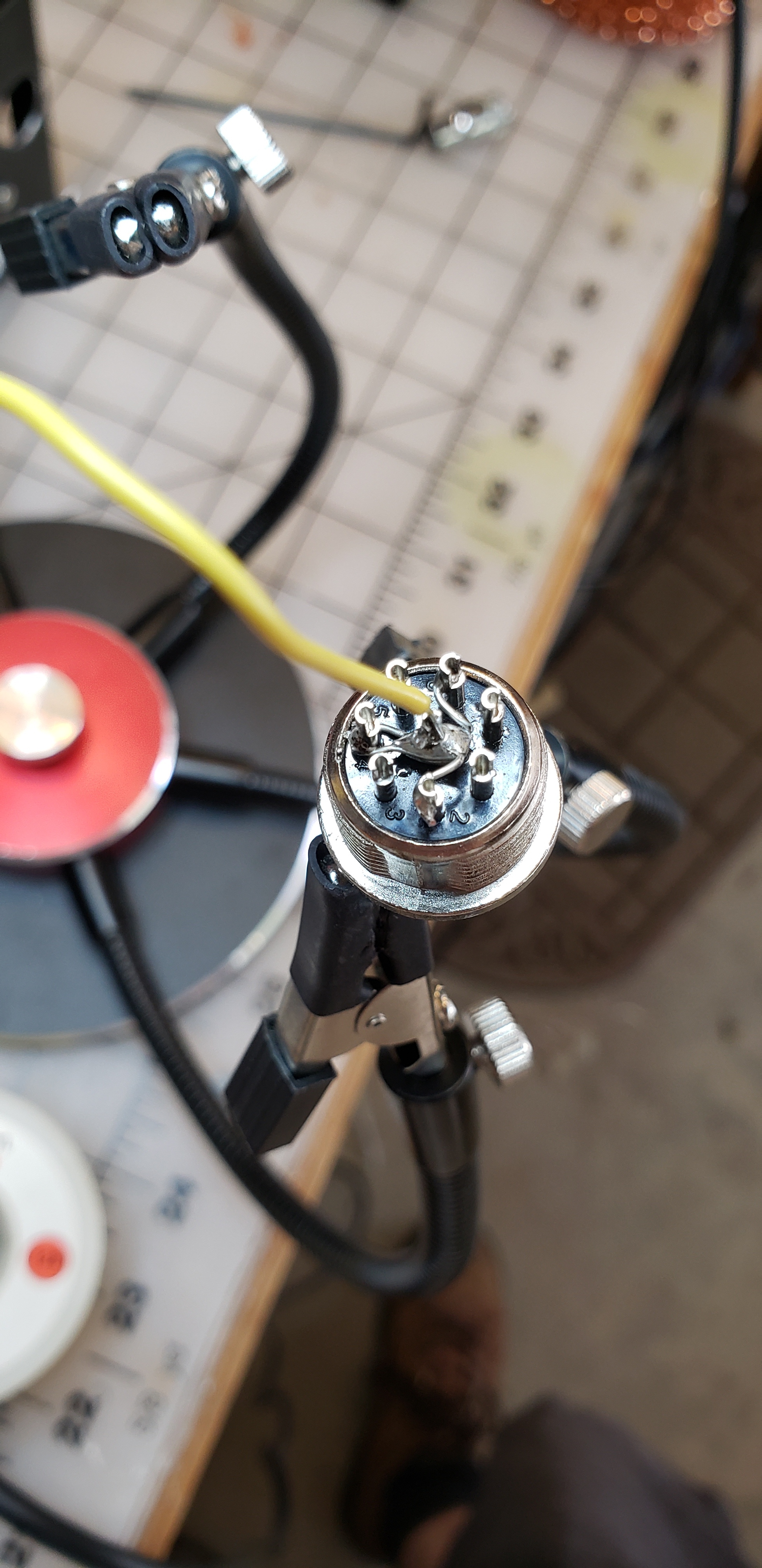
The even number pins were connected with the same crimped connectors to the IN1, IN2, IN3 and IN4 pins on the controller board (see pic above.)

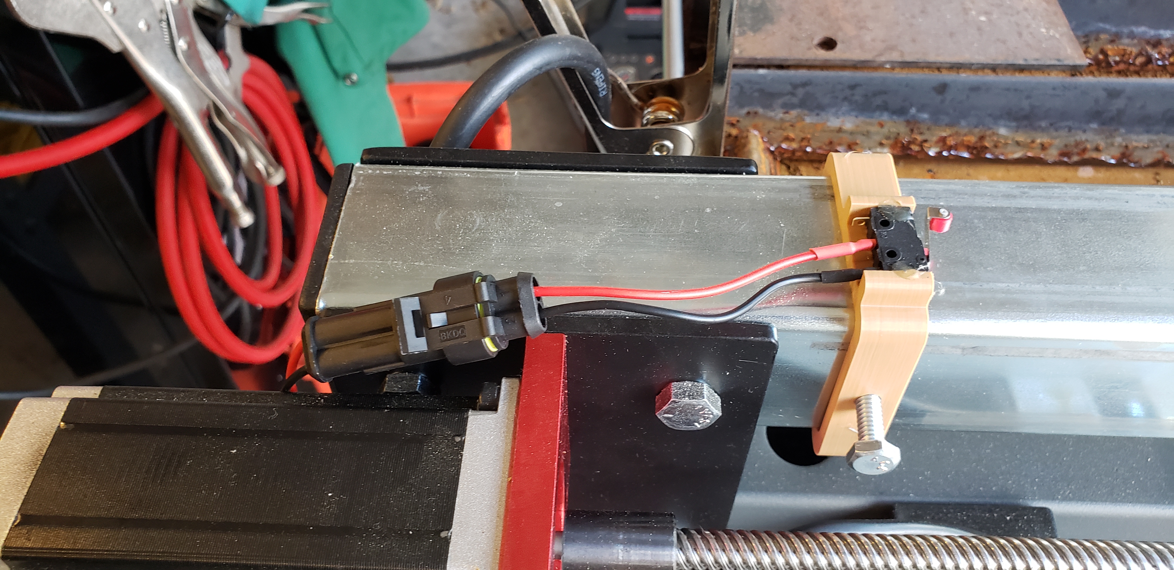
I 3D printed mounts for the limit switches:

I used momentary contact switches hot melt glued to the 3D printed mounts:
https://smile.amazon.com/gp/product/B00MFRMFS6/

Each of these has an automotive connector at the switch for easy swap out (and to be able to clear the limit alert when tripped.) Any connector will do. These are waterproof which is helpful with the water table splash.
https://smile.amazon.com/gp/product/B0144CFQFS

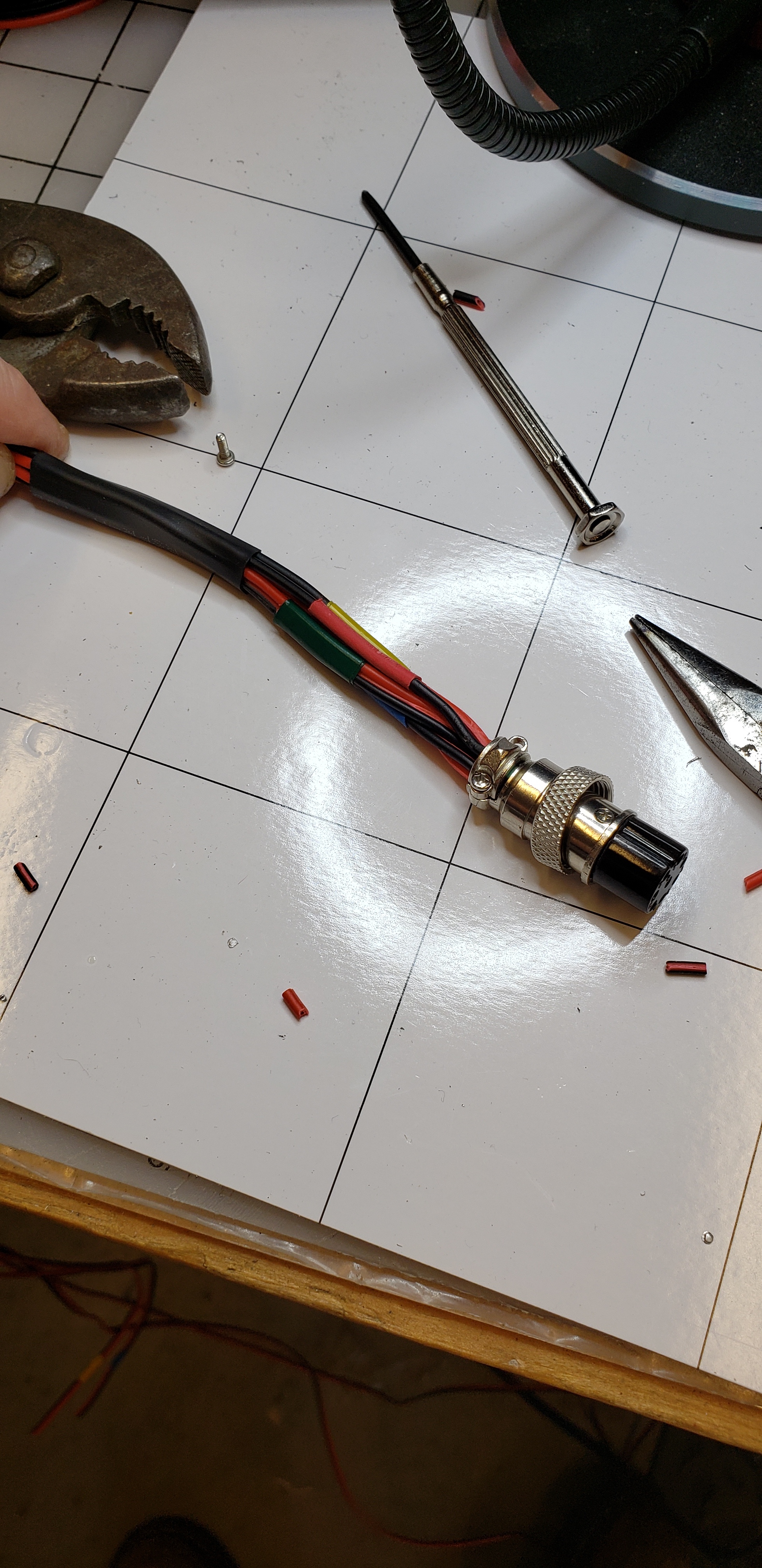
I ran paired wires back to the connector and soldered them to the other side of the aviation connector:

To get this to work in Mach3 I had to make changes in two screens. The first was Config/Ports & Pins/Input Signals. Set the port number to 3 and use pin numbers 1-4:

The second screen was Config/Homing Limits. Here I had to change Reversed and Home Neg:

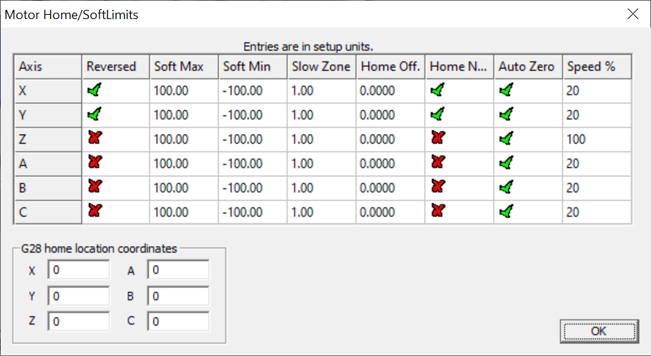
With all that, the switches are operating as expected both as home switches and limit switches. Mach3 does some obscure stuff with moving off the home switches after homing, but play with setting X & Y Zero to help with that.

I hope that makes it easier for others than it was for me to add home and limit switches to their Crossfire!

5 Likes

Good write up… I added limit switches to mine following some of what tooljunkie did in his YouTube videos… I should have went the step down route instead on adding an additional 5v/24v power supply… either way it works…

I figured out the issue of it backing off the switches about 1/2 inch after it homes… you have to edit the crossfire xml file in mach3 and look towards the very bottom and you’ll see a few lines referrencing the X & Y axis pull off or something like that… it’s set to .5 I believe… just change it to a lower value to get it closer to the home switches.

1 Like

Great tip on the XML!

I’ve come to really like using buck converters for stepping down VDC. They’re cheap and produce way less heat than linear regulators (more efficient too!) While I couldn’t find a fixed 36V-24V model, the adjustable works great and I’m a sucker for the voltage display.

NOTE:
The reed relay that turns the torch ON/OFF uses OUT4 from the controller board. OUT4 is active LOW and it is only switching against the 24V that I provided to the INPUT lines on 24V and DCM. I’m investigating if I can tie the DCM (Ground) to the 5V ground or I need to swap the reed relay for a 24V relay. I will edit the article above when I have a clean solution.

I used a 24v relay that tool junkie listed on his parts list.

1 Like

Researching the board that the Langmuir BOB is based on, it’s clear that they intentionally isolated the input/output lines from the 5V USB power. Not a bad plan. While the grounds are shared back at the power supply, it’s still a good idea to follow tool junkie’s lead and use a 24VDC relay as the board designers intended.

1 Like

@tdeagan

I noticed you said,

“Each of these has an automotive connector at the switch for easy swap out (and to be able to clear the limit alert when tripped.) Any connector will do…”

Well I was just watching this, https://youtu.be/TmLIcV9G_Bc and around the 7:35 mark he explains the limits override button. Then I remembered this post. Maybe you should try to do a limits override to jog off your activated limit switch? That way you don’t have to unplug a switch.

1 Like

I already soldered the resistors on top of my inputs to support 5V. I agree to is probably a good idea to keep the inputs isolated from the usb 5v. I have some buck converters on hand and I might use one to supply the 5v for the inputs and output relay.

I’m planning to add limit switches and an e-stop to mine as I am apparently incapable of using the jog function without running up against the stops. What is the connector on the stock control board called? I was going to buy one to fit, but I don’t know its name?

The connector for the IN1-IN4 signals?

Yes.
As near as I can measure, it’s 0.050" (1.2mm) pins on 0.2 (5.08mm) spacing.

I couldn’t find the connector and ended up connecting directly to the pins. I used female connectors (from pretty much any kind of connector system; JST, Molex, etc.) crimped to the wires with some heatshrink as a shield.

just buy an extra MCB with the screw type connections.

This one will work… straight swap.

I don’t know the PN for the exact connector LG used, but an equivalent is:
Molex 10-01-3046, Mouser 538-10-01-3046
The matching crimp pin is 08-70-1031, Mouser 538-08-70-1031.

Bear in mind that the IN1-IN4 pins are rated for 24V input, 5V input won’t trigger them with changing resistors on the board. Further, LG has wired the IO supply to the 5V USB from your computer so that creates an additional load and less isolation on the Limit switches.

12V is sufficient to trigger the signals, but, again you’ll need to rewire the supply to the IO section.

Thanks guys. I ordered a set from Mouser. That way I’ll be able to add my limit switches without modifying the original harness (I think)

I got my E-stop and limit switches installed and working. I used the connectors from Mouser to connect to the OEM board. I added a buck converter to derive the 24v from the stepper supply and used a 24v relay module to control the torch. I mounted them on the cover of the stepper supply. I used a GX-16 connector to bring the wires out of the case. I modified tdeagan’s limit switch mounts on Thingiverse to use the larger microswitches. I made a bracket to attach the E-stop switch to the end of the y-axis beam.
So far it’s working. The carriages and lead screws seem to appreciate not being banged into the mounting nuts at the end of the beams.

Thanks again for the help and inspiration from this thread.

2 Likes

Thank you for writing it in such a detailed way. Quick questions since I am new to the whole thing.

1- does this work on Fire control?
2- how many 3d print parts would I need to print?
3- what is the size of the standoffs you used?
4- any changes or updates you have made or wished to make, and would you be recommending?

Most likely, I follow your guidelines here!

Won’t work with firecontrol. This is meant to work with the older Mach3 version tables.

can someone help
do you hook each axis signal separate IN1 for Z IN2 for X and IN3 for Y ?

I have all the limit switches connected together to the same input. The auto homing in Mach3 seems to know which way it was going when it hits a limit and interprets it correctly. For the purposes of auto stop, it doesn’t matter – I always want the machine to stop no matter which limit it hit.

regards,
Leon