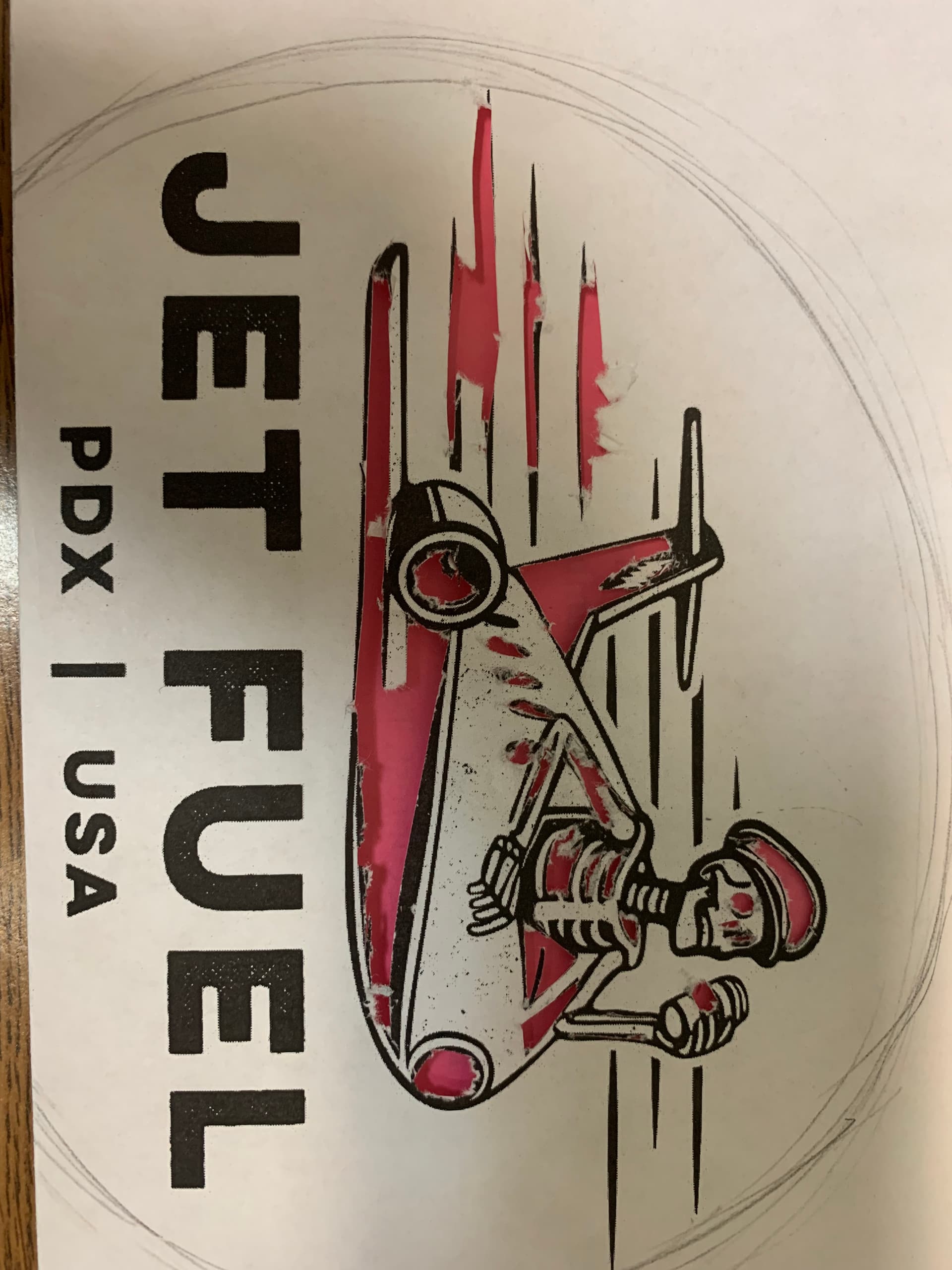
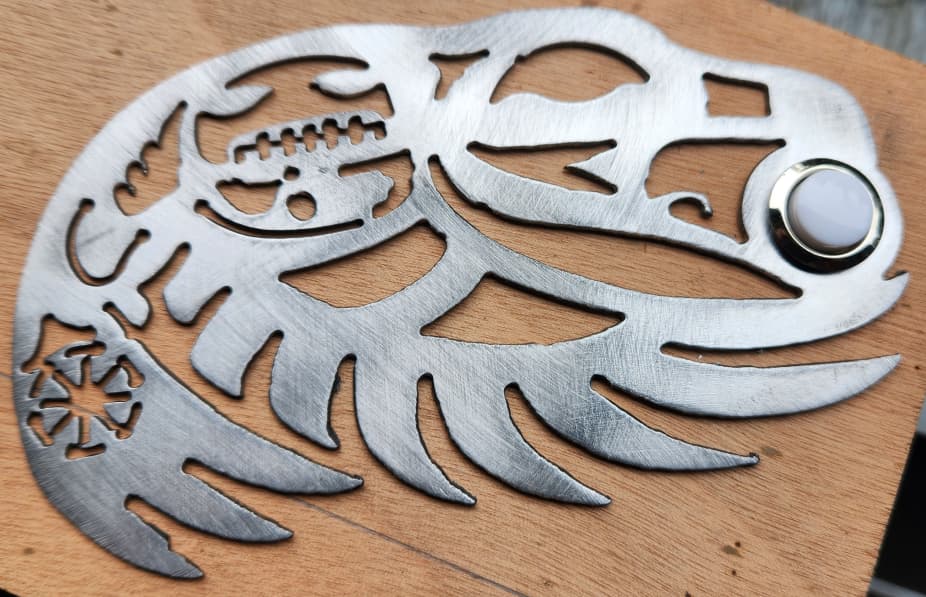
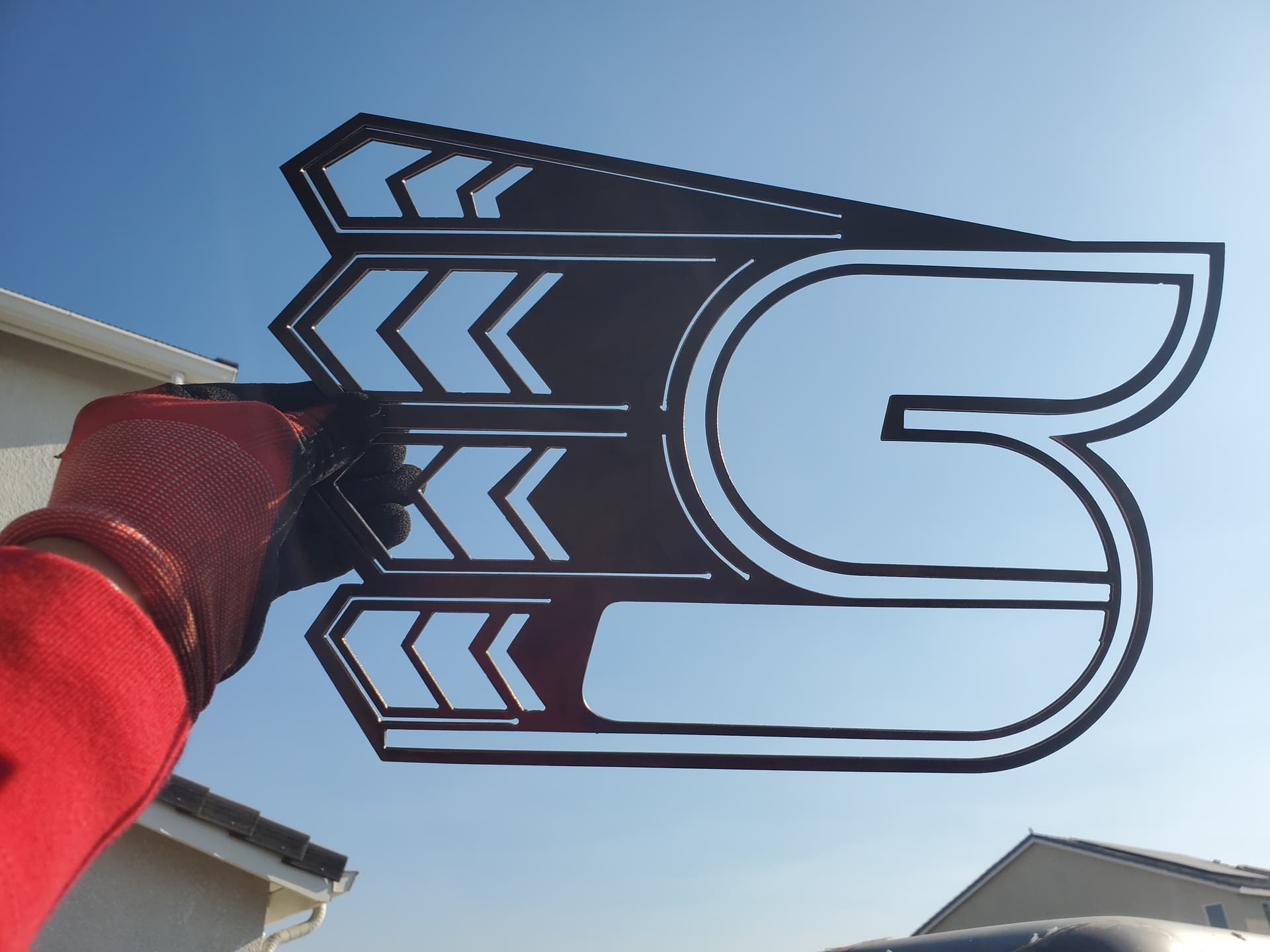
My neighbor asked if I could cut this design out for him. I converted it to an SVG and cleaned it up a little.
I am having a hard time understanding or visualizing what needs to get cut out and what needs to stay. Looking at the skeleton and airplane I think it would make sense to cut everything that is in black and leave everything that is in white.
I have extruded the image, and I get the opposite of what I am looking for. All of the white wants to cut out and it leaves the black.
I am just not sure how to keep the pieces I want. I am thinking I have to close lines and connect pieces to the outline of the plane, so they don’t fall out? i.e. the lightning
I hope I am on the right track. This seems to be one of the more complicated pieces I have tried so far.
I uploaded an example of what I was thinking. The picture with the pink piece of paper shows what I want to be cut out. Did a rough cut-out so I could try and visualize it.
I have been working on bridging pieces slowly. I go back and forth from bridging to checking with extruding it. Then I go back and bridge more. Just takes time to get my bridges in the correct spots.
I was wondering if I could get some input on what looks good and what is questionable. My concern is the small lines that are close together may interfere with each other.
If it shows that it will cut a line in Simulation mode does that really mean it will cut on the plasma table?
Need a bit more information as I am not sure of your intended size. What cutter and consumables are you using?
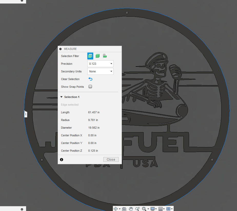
To insert the dxf, it comes into Fusion at just under 20 inch diameter.
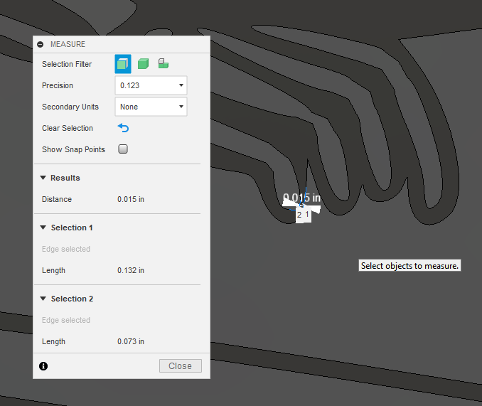
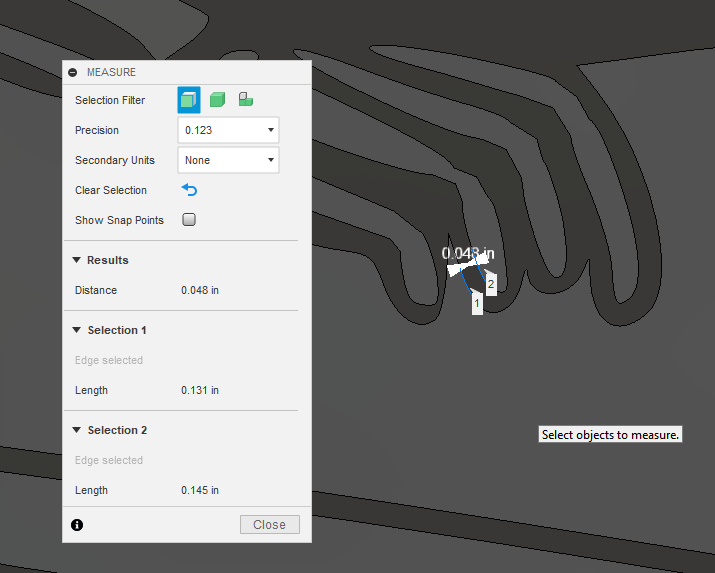
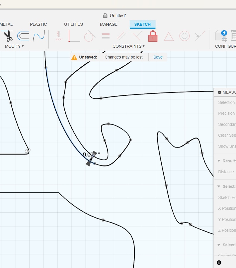
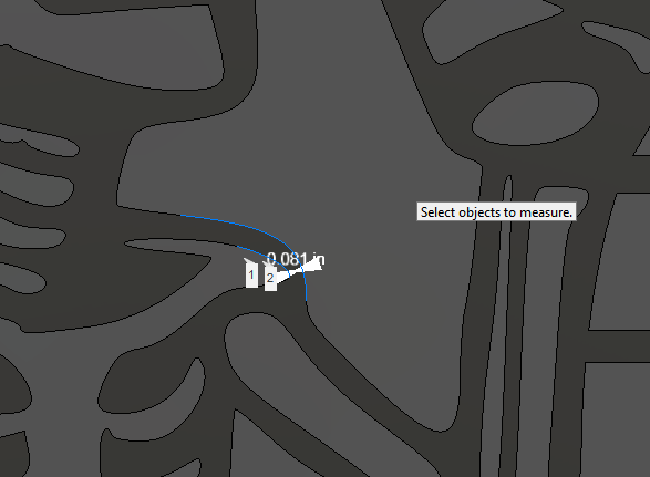
I took a quick look and there are areas like the fingers were the metal is not going to survive. You need at least 0.11 inches of metal to reliably survive being cut from both sides. Occasionally, you might get lucky with 0.07 inches but don’t count on it. The little finger will not survive:
So, after talking with my neighbor again today he is ok with the sign being made larger. So, my thinking is taking the smallest area and scale it to 0.11 inches and everything should survive the cuts. Not sure what size the entire sign will be yet, but I guess I’ll find out.
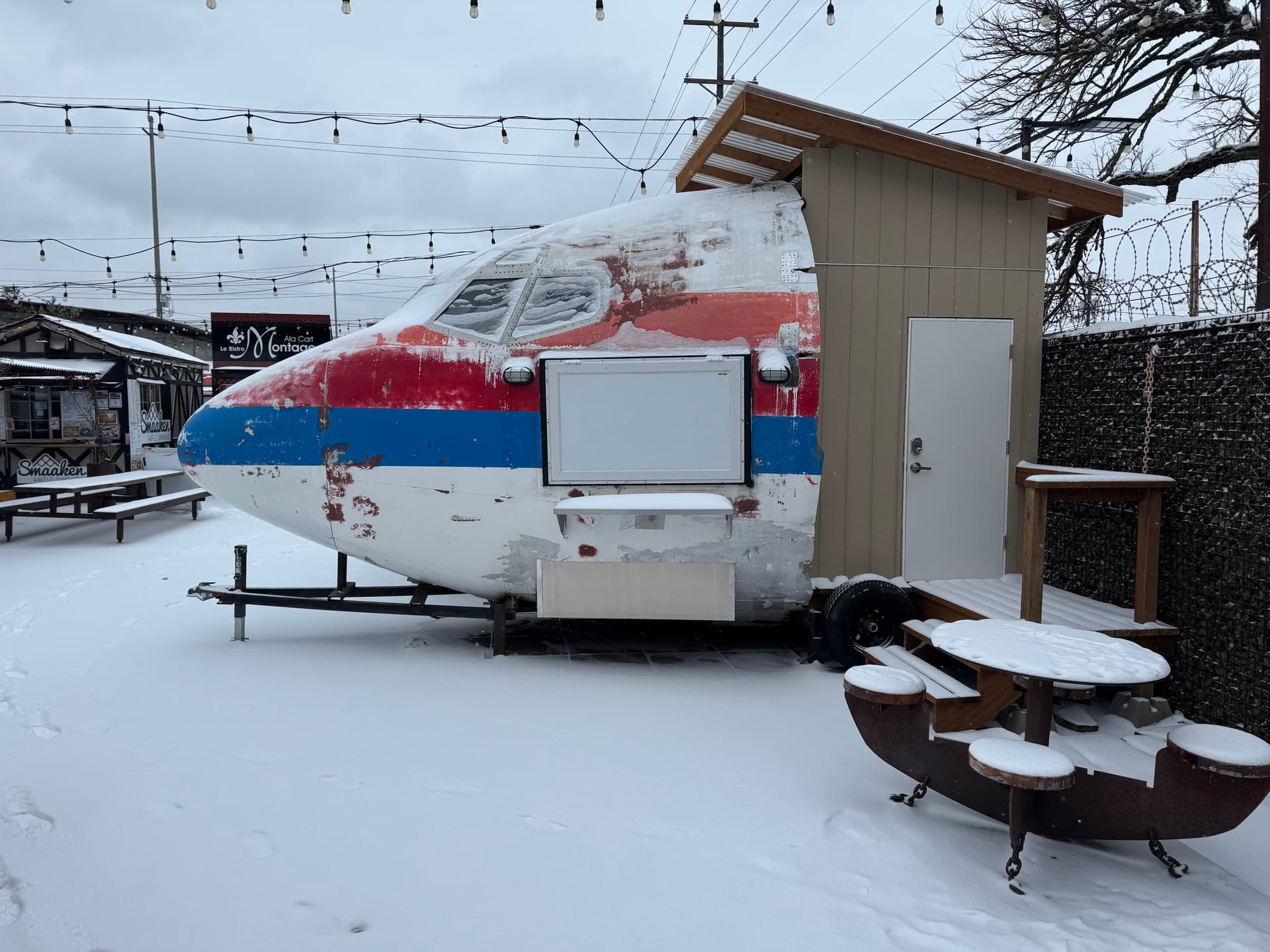
The sign is going to hang on the side of this DC8 nose. It is in a food cart area and will be serving coffee. The original plan was to have it small enough to sit on the counter. I found that to be a no go. So, now he going to attach the sign to the side of the plane under the windows.
Just to give you more of an idea with the size, my guideline of 0.11 inches WILL survive the cutting process in most instances. As Tin and Bret are saying, you might get by with less of a margin of size. I have even had pieces that were 0.07 inches survive but you have to be careful with it and it all depends how your piece is going to be displayed.
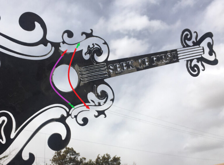
This picture shows some very small areas that did not survive on one side of the guitar but did on the opposite side. The green arrow heads are showing “survivors” and the red arrow heads show where the metal was burned or fell away. (It can also “fall” away during the cleaning process to remove dross and finish the sign.)
Note: In no way am I trying to pick on this person’s work. I have done things that are much worse. This is only for illustration purposes.
Here is another example of something I did. I could not get all the detail I wanted so I had to simplify the details: still leave the same impression without all the pieces.
This is what a friend wanted for a door bell plate cut out of metal:
This is how I had to reduce features. It lost lots of the art but they were still delighted and I would do a better job today since this was when my cut height was wrong and the lead-ins show. (Perhaps not a great example!!!)
For your skeleton, the right hand is a bit of a problem and you might resolve it by making it three fingers instead of four. Some of the other areas just need a little redrawing to make the piece thicker.
Use all the tools at your disposal: Make it as big as your custormer wants or tolerates and then modify those areas you still find.
I am going to go in and make some changes to the sketch in order to make pieces a little larger. ie. the parts inside the hat.
I can also scale the sketch larger. Neighbor is OK with sign being bigger and hanging on side of pane.
Although, I have been trying to scale the sign larger and then it messes with the sketch and seems to make some crazy lines on the sketch. So, I am working on that.
Is it better to scale the sketch in Fusion or in FireControl?
Thanks again for all the support! I really appreciate learning the process!
1st attempt ended up being a failure! I made some changes to the sketch, thinking I was making it better but ended up making it worse. The entire head fell.
I went back in and reverted back to the original drawing.
I deleted parts of fingers and tried to go through and triple check that I had at least 0.11 clearance between all lines.
So, when I create a model and view the model all areas of the sign in brown should be the parts that stay everything in white should get cut out. Is this correct?
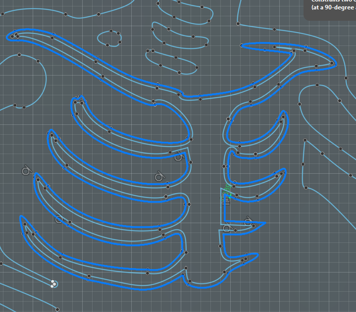
So I clicked on the entire rib cage (required some fixing of the sketch) and then did an offset inward of the rib cage, then delete the original rib cage line:
After deleting the original rib cage, the lower ribs on the right needed some added definition so you could add some single curved lines. You can also see that we now have added metal to support the head:
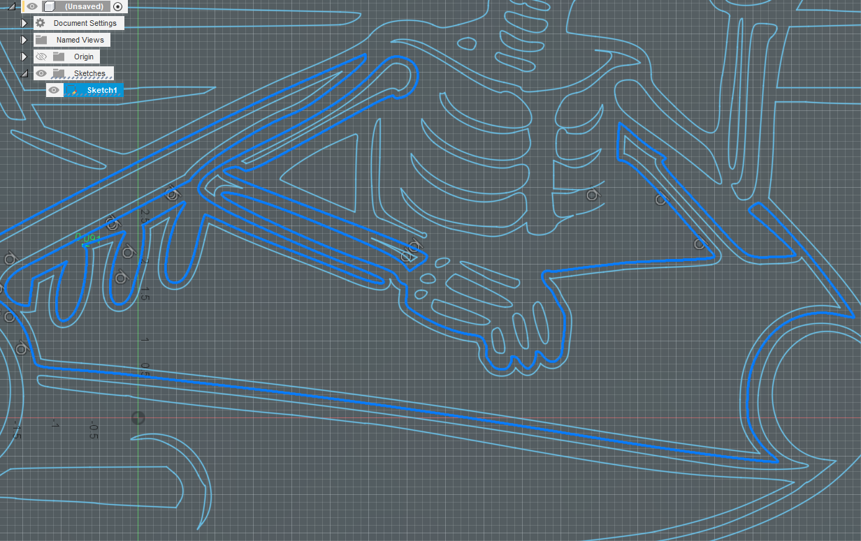
And if you want to get more information and less empty space, you could go renegade on the design and move the entire border inward. This gives the message more bang for the buck and is just under 29 inches.
Thank you for taking the time to help with this design. It is super appreciated! This is such a great learning experience for me as a beginer with the CAD and CAM process.
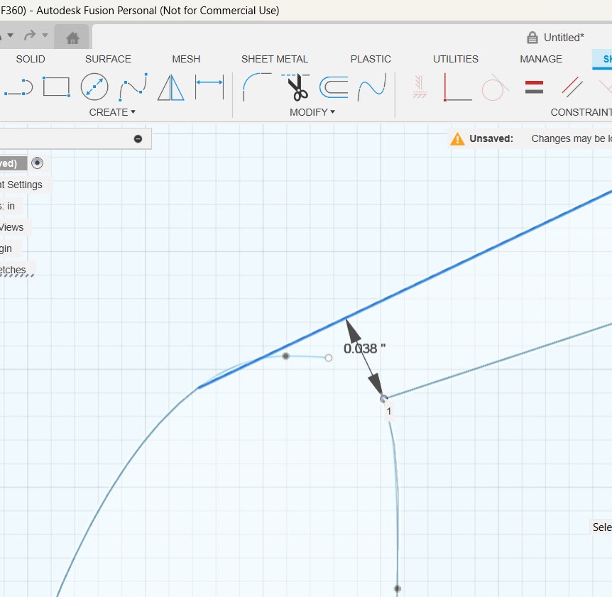
OK, so I see at the acromion bone when you measured it was only 0.81. So, not enough metal to really hold it together. So, for the future measure all suspicious areas to make sure there is enough metal in order to hold it together. ( 0.12 will give adequate strength )
Rib cage: I never thought about offsetting the rib cage like you did in order to shrink it and then give more room for the acromion. Then added to the lower ribs in order to make them look complete. I also see you circled in red 0.127 will give adequate strength. Knowing that number is very helpful.
Fuselage: So, you did the same thing offset the fuselage in order to make is smaller and give more support.
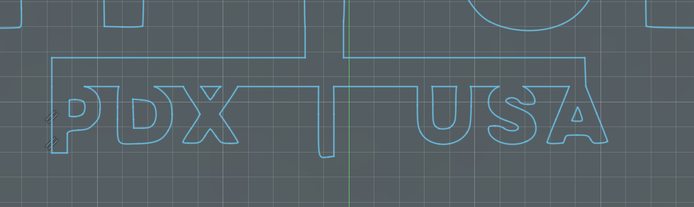
Letters: OK, thank you, I thought it seemed kind of redundant. Thank you for the clean-up of the letters.
Again, thank you for taking the time to explain and help with this design. I really appreciate it! Having this help is invaluable to me!
Thank you for your reply. So, an open chain would allow me to select just the lines that I want to cut? So, would that mean you can use open chain to break up closed chain loops?