How difficult would it be to draw a gear in Fusion. I’m honestly not real sure where to start. The chain pitch is 1/2" and the chain rollers are 5/16" and I need a 45 tooth gear. Anybody smart enough to figure out how to draw that?
Go on mcmaster carr and find your gear/sprocket that you need. Download the step file and import it into Fusion.Then you can create a sketch and copy the cross section.
7 Likes
Just search on Youtube, there are a couple tools in fusion that make sketching gears extremely fast and easy. I don’t have access to Youtube at work or I’d post a link. Should be easy to find.
I think what you’re looking for is called a sprocket…(If it’s used with chain…) ??
You can give this one a try…
sprocketA.dxf (12.6 KB)
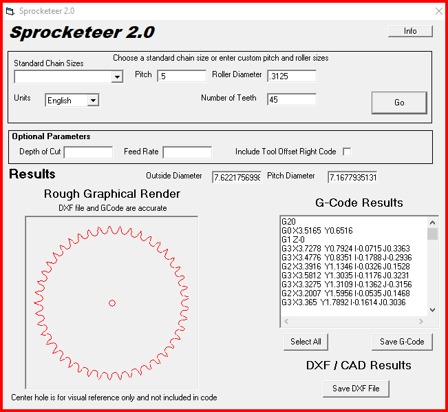
Neat little program called “Sprocketeer 2.0”…
2 Likes
It’s already been discussed here how amazing the gear generator plugins are for fusion, so there isn’t much more I can add on that front… but what I can say is this… there aren’t many people out there who COULD manually draw a gear or socket (with the proper geometry) without having to scrap 4 or 5 different versions along the way.
The math alone involved in getting the perfect pitch and involute so that the contact area of each tooth isn’t binding or rubbing, or has too much slop etc.
Every scratch designed gear I’ve ever see made has involved hand drawing a scaled up version of a single tooth using protractors and a ton of trigonometry.
Those plug in’s do the insane amount of math for you, on demand, and they are able to generate the perfect gear profile for your application in no time flat!
If a generic profile is what you’re after, downloading the step file from McMaster MAY work, it’ll still be an approximation (depending on how the file was output and re-rendered on your machine) but for a low precision application, it should work just fine! If you’re looking to make a gear for a high-speed application, or for use inside of transmission or something, then you’ll almost certainly have to machine one from a billet on a mill, or hob one using a gear hobbing machine.
1 Like
I actually use a program called EmachineShop. Give that a try.
1 Like
I did this a few years back and what I did was first use Inkscape to create a vector drawing. It has a gear generating feature good google video there. Once I had the vector I imported it into Fusion360 and mapped it to the face of a material (google video too). Then in Fusion I generated the G code in the CAM section. I then went back multiple times edited the teeth in inkscape and adjusted the size in Fusion. It’s obviously pretty simplified, and if your trying to match an existing gear it’s going to be way more work, but if your cutting all the gears you can make sure they mesh in Fusion before you cut them.
1 Like
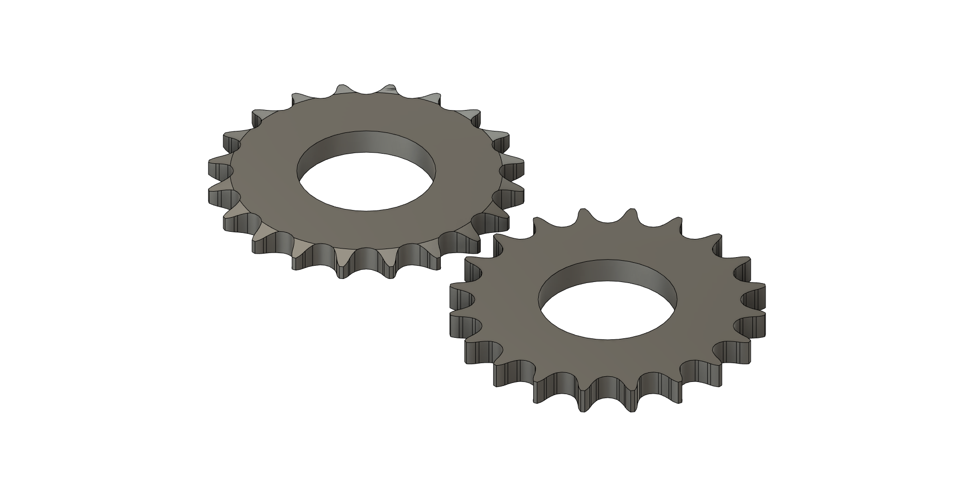
I have a part that I sell that includes two small laser cut gears that drive on each other. I designed it in fusion using the gear tool. It’s pretty easy to do. I found a video on you tube that explains it all. My gears work really well together but it did take some tuning to get them to cut and mesh properly because of the dross / cut quality.
If it is a sprocket you are looking for, I have had some success with them in Fusion360 (Two of them are posted on the FileShare).
I will say, however, that the dimensioning of them is quite a crap shoot due to the different kerfs on various cutters. It is a trial and error thing for sure. 1/100 of an inch in the roller pitch, times 40 or 50 teeth and the chain won’t fit properly.
Granted, to do them properly there is a lot of math involved (as mentioned earlier) but for 2D cutting this simple way has worked for me.
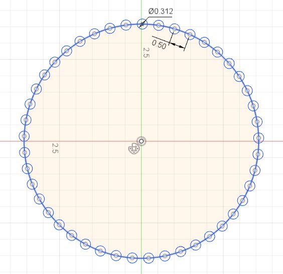
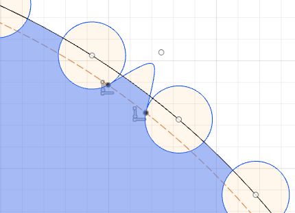
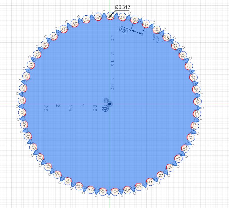
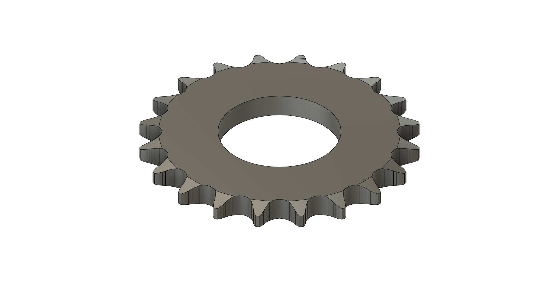
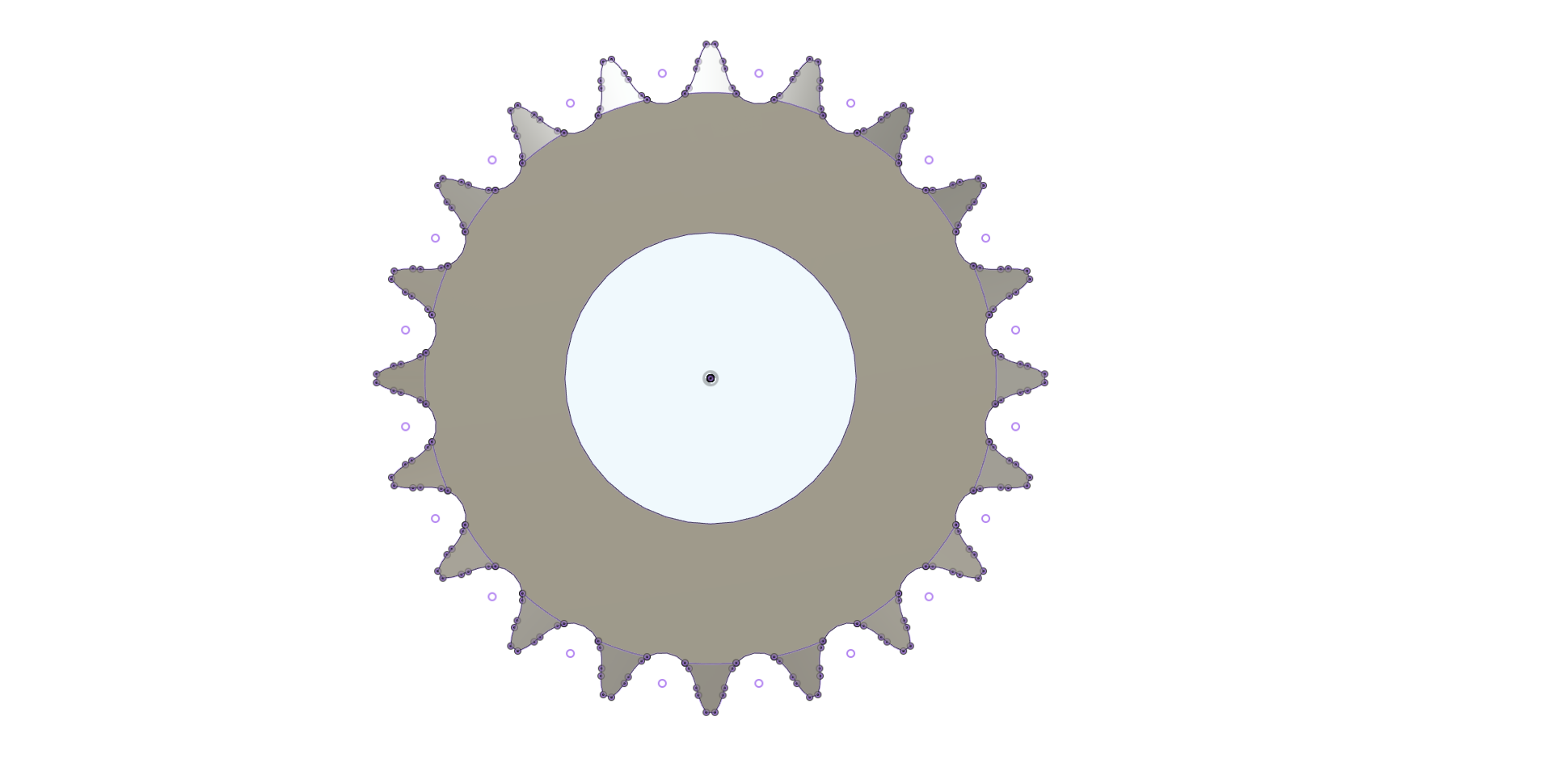
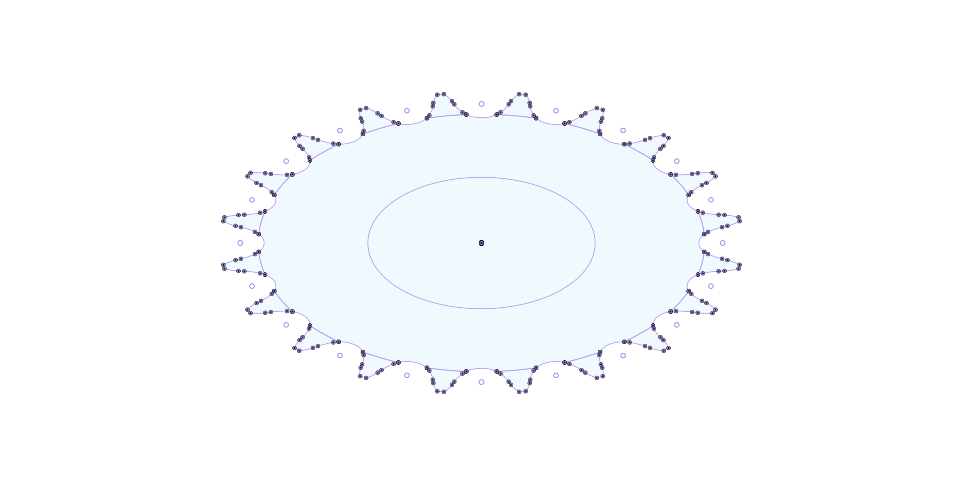
Basically you create a circle, then draw one roller on the circle and use the “circular pattern” tool to set number of teeth. Dimension the “pitch” and let it drive the larger circle dimension. Then draw one tooth (I just use the conic curve for this) and use the circular tool again. Change the large circle to a “construction line” and the piece should fill in. Extrude it before you post process.
I taper the edges of the teeth with a belt grinder just slightly after it is cut out.
If you Email me, at dc245@hotmail.com, I will send you the Fusion360 file I used for this post so you can play with it. (put 'sprocket" in the subject line.)
Sprocket 45 tooth 40 chain.dxf (29.5 KB)
3 Likes
i have tried this but it wont allow me to change the bore size ![]()
Use the center bore to simply give you a center point on your sketch and then create a new circle, using that center, but with the bore you want. Just be sure to select all the faces necessary to extrude your sprocket.
2 Likes
Thanks, I will try it again. hopefully I will have better luck.
There’s always “Sprocketeer” to try as well…
EDIT: OOPS… I see I mentioned this above… thread’s been around a while I guess!
2 Likes
hey Daniel, i got the bore that i needed on the sprocket but i can’t get the teeth to extrude . your help will greatly appreciated.
Can you export and post your F3D file from Fusion 360.
It would help narrow down your extrusion issue.
sprocket v2.f3d (342.9 KB)
This part is already extruded.
I projected the geometry to a new DXF then extruded that which gave me a gear without the chamfers.
sprocket v2 truely flat.f3d (768.4 KB)
is that what you are after?
1 Like
yes it is , thanks so much,i have so much to learn lol
You’re welcome.
P is the hotkey for project. FYI.
now to get it into fusion. lol wasn’t that hard lol thanks again Tin Whisperer