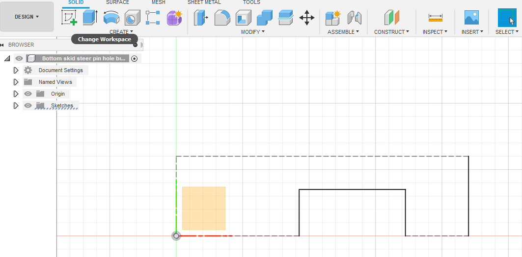
I am a new user of CAD software period, so here I go…I have a piece of flat bar metal that is currently 3" wide and 20" long…and all I want to do is make the total length 11" and then cut a notch in one side of it that is 4" long. I sketched the total dimensions of the 3x20 flat bar and converted only the lines that I want to cut on…to construction lines, because most of the perimeter lines are fine, since I am starting off with a piece of flat bar that the dimensions are fine except I need a certain length and then a notch cut in it. The file looks fine in Design in CAD but when I go to Manufacture and click on the 2D and try to do the cut path…the entire perimeter of the drawing is being selected as one big cut path, which is not what I want. The image labeled ‘Design’
is how it looks in the Design view and you can see where I have made all lines where I don’t want to cut, the Construction lines. The image ‘Manufacture’
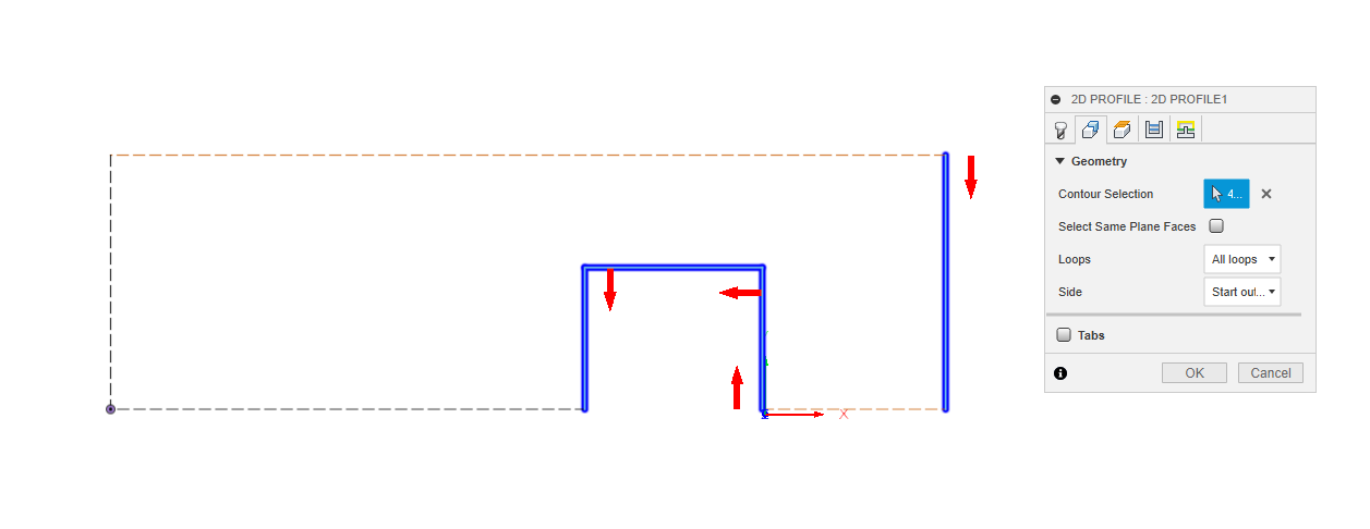
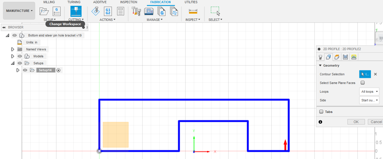
is where I am in Manufacture and clicked on defining the cut path and it shows that the entire perimeter
is selected and wanting to cut all of the outside lines. The image ‘Desired cuts’
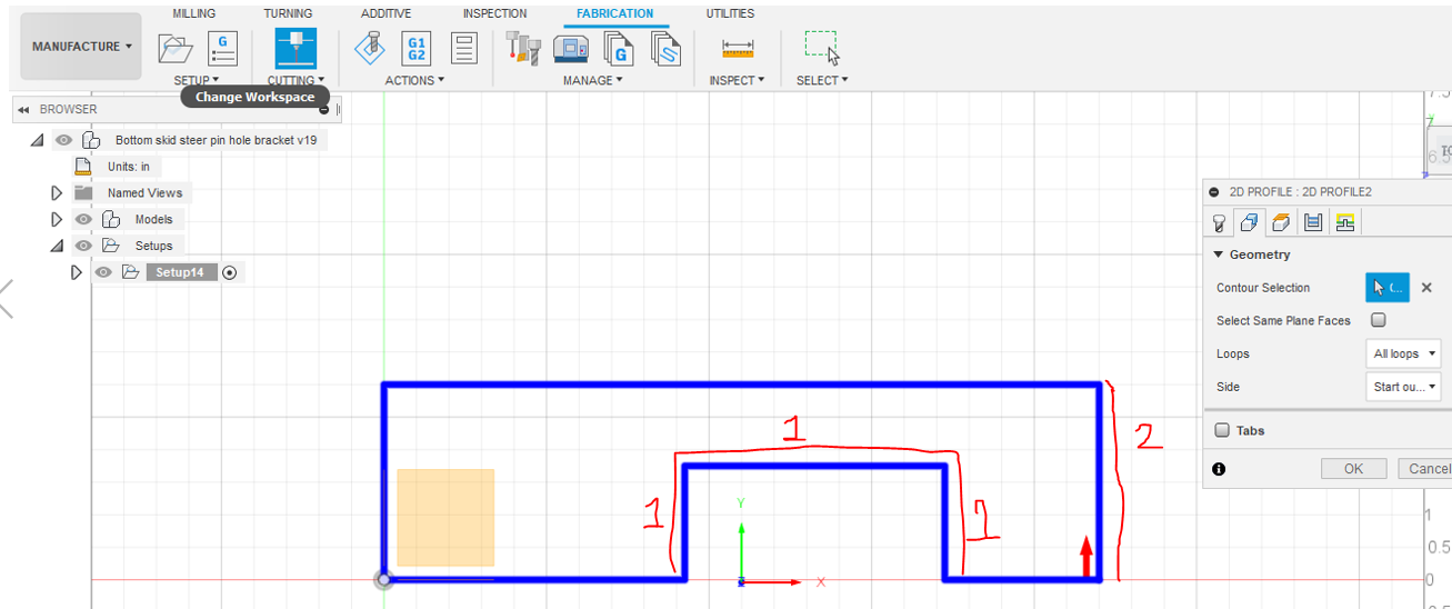
is where I marked up the screenshoot to try and show the only places where I am wanting the piece of metal cut at…the lines that I have marked as 1, which is the notch I was referring to, and then the one right side marked as 2, which is the 11" mark where I want to cut the metal plate all the way down at. I hope this make sense. I am wanting to draw the whole part but yet learn how to do the cut path so that only parts 1 and 2 are on the cut path and not the entire perimeter.
And finally why is the XYZ axis correct in Design but when I go to Manufacture, the XYZ axis is in the middle of my part?
For something that simple I’d just hit the straight line button in fire control. Enter x or y axis and length. You can etch a sketch almost anything with straight lines using that…
As for the cad… Not the easiest way to a crest a cut… 2D through cuts are super simple, and it seems complicated how you’ve put it all together.
I use a locating square to set corner of material at 0,0 if I’m not doing a final perimeter cut. Think knife stock cut down to size and pin holes punched… Only xray the lines you want cut and place a dot at 0,0 so it sets origin to your 0,0 corner of the material.
Thank you for the response…with what I build, this will be a common scenario for me. I have a piece of metal where the perimeter dimensions are correct, but I just need to cut the end straight or at an angle and then will need to cut notches some where down the middle etc… I am wanting to learn the concept of the best way to handle this of drawing the complete part/piece of metal in CAD and then define the cut path only for certain lines. Is this not what construction lines are used for… to outline a piece of material or to make a measurement but not to cut on ?
Id be happy to look at how you set it up and drew. You can share the fusion file with me… If you know how to export your cam settings for the CrossFire, I’ll do same setup cut and give you some feedback.
In Fusion 360, you are just wanting me to grab the saved file of the part I drew up? Is that all you are needing ? Not sure what you mean by exporting the CrossFire CAM settings.
The easiest way to do it is to do your construction lines and your cut lines as two different sketches, then just hide the construction lines with the eyeball in the manufacture workspace.
Yes, to do what you are trying to do, I would draw the whole thing in one sketch with construction lines. Then I would start a new sketch on the same plane and just trace on top of the lines you want to cut with regular lines. Then when you go into the manufacture workspace, just hide the one with construction lines. You should be able to just select the lines you want to be cut and not the others when you make your cut operation, which would negate all the redundant work.
That is awesome…and I will try to figure out how to over lay the two sketches…thank you! I guess there is not a hot key per say but just draw the full thing with construction line then go back and pick solid line and just draw my cut lines. I wanted to be able to lay my metal down and then load my program and it go over to the top right corner which would be the 11" from the left corner end…instead of me having to lay the piece of metal on the table already at 11" and be up under the torch.
You are correct in what I am trying to learn. In the Manufacture picture I posted above, when clicking the Control Selection and then clicking my part…the whole thing got highlighted as a cut path even including the construction lines. But you are saying I can click while holding down the altar and then just click the individual lines?? I will check that out. Thank you.
That worked great! So I built my entire part using Construction lines and then when I went to 2D profile for cutting…I held down the altar key and selected only the lines I wanted to cut and it allowed me to only highlight the lines I clicked. Prior to that I was not clicking alt…just clicking the contour selction button and then clicking my part and it was highlighting all of the peremiter lines. Thank you all again!
 I’ll check back later