I have my Pro up and running. No cuts yet just learning Sheet Cam and Firecontrol with dry runs. I notice when I run a program from hard 0/0 stops I am losing position because I believe the machine is not allowing for the kerf and bumping against the hard stops at the bottom and left side of the runs and losing position by the width of the kerf. Is this something that can be fixed in Sheet Cam or Firecontrol? I can avoid it by bumping the start position in by 1/4" but I shouldn’t need to.
if its hitting the stops the motors will loose steps. the software and controller has no way to know if the motor completed the whole move instruction. if the controller says move Y 100 steps and something physically blocks it after its moved 75 steps it will loose the last 25 and continue the program from the wrong place
1 Like
Fundamental law of nature: Ya can’t move past the stops. The table just won’t do it.
If your design has lead in/lead outs that extend beyond the Min X or Min Y dimensions then you must offset the design deeper into the table.
That is not to say that you MUST extend deeper into the material, you could offset the material, but then you’re pierce occurs off the material and that’s not a good thing. You could also edit your starts to occur elsewhere in the design and therefore avoid the stopped edges.
1 Like
I understand the physical nature of not cutting past the hard stop or limits of the machine. Once the cad drawing is tool pathed or post processed Sheet Cam or Firecontrol should recognise the increased size of the part because of the kerf and lead in. I also have a Torchmate machine and it does just that. Maybe there is a setting in Sheet Cam but I’ve barely scratched the surface with knowing that program. Or maybe it is something that needs to be addressed in Firecontrol.
I don’t think it’s good to run the x y to the hard stops. We don’t have limit switches, isn’t there a small chance something would break?
It makes sense to me that I would lose 1/8 or 1/4 inch of travel because I don’t want to slam against the stops.
It’s not harmful to run the Stepper motors to their stops to zero them out. I operate and repair automated lights for theaters and as part of their start up and homing most of them bump their functions at a hard stop. They make a fair amount of noise during this process of homing. I also have a Torchmate growth series table I have been bumping against the hard stops to zero the table for 8 years. The noise you hear is not grinding it is the magnetic pulses trying to advance the motor even though it is against a hard stop. I wouldn’t advise slamming into the limits full speed either, get close slow it down and bump it in.
My purpose of this thread was to find out if there is a way to get sheet cam post processing to recognise the Kerf and Lead in as part of the whole part. Right now if you start from hard stops it doesn’t allow for the Kerf as part of the cutting process so when it comes around to a hard stop it bottoms out by the width of the Kerf and throws the rest of the program off. Right now I zero to hard stops then using the step feature I bump it in 1/4" from each stop and set zero before cutting. This works but I shouldn’t need to.
I have noticed that sheetcam will show the kerf outside the workpiece. I never though much about it but what you’re saying makes sense.
Just curious, I think there are a few people who have other tables in addition to the Langmuir.
Why did you get the crossfire if you already have a higher end table and do you notice any difference in cut quality between them?
I’m glad someone noticed the Kerf problem other than me. You probably would never notice if you are just cutting random pieces from the center of the table but I use a fence and start from hard stop to get maximum use out of my steel.
I wouldn’t call the Torchmate Growth Series a high end table, it started as a 2x2 hobby table and came with no stand, no slats or slat holders or water table. It was ment to be portable, you could set it on saw horses over a metal trash can or whatever and cnc plasma cut. It had a hand crank height control. Just like the Crossfire started out as an entry level 2x2 table but soon users wanted it bigger. So Torchmate made a 2x4 then 4x4, I jumped on the first edition of the 2x4. They sold an automatic height control but it cost more than the table. Then Lincoln bought Torchmate and they dropped sales and support for the Growth Series table. My 8 year old warhorse still works well, it’s cut a lot of steel but it’s showing it’s age and no longer is supported by Torchmate. I happened to see something about the Crossfire and thought that’s cool and cheap but too small. Then I saw them coming out with the Pro with an amazing introductory price and inexpensive height control so I had to have it. I have cut the same part on my Torchmate and Pro and I see no difference, they both cut well and I haven’t even hooked up the height control yet.
So you’re seeing the tool path outside of the programmed part? Are you choosing inside or outside offsets? If you use outside offset on an inside cut , it will def. be bigger and tool path will be outside of drawn path.
I draw/color inside cuts in one color (red) and outside cuts in another color (green) and no offsets still another color (yellow) this way sheetcam will give you 3 “layers” and you can program each “layer” individually. this will allow inside/outside and no offsets at the same time.
Also be aware 1st operation listed is the one done first
1 Like
I’m not having any problems with tool-pathing. This was just about the kerf showing off of the workpiece on the view as you are setting everything up. It’s not really an issue unless you can’t afford to lose .053 off your design. maybe @mr540602 can explain it better.
ah, I am no where near the edge, maybe 3/16, I know what he means now lol, I didn’t think about getting that close to the edge of material, so I thought he meant program lines not material edge, I guess it does add up
Yeah this.
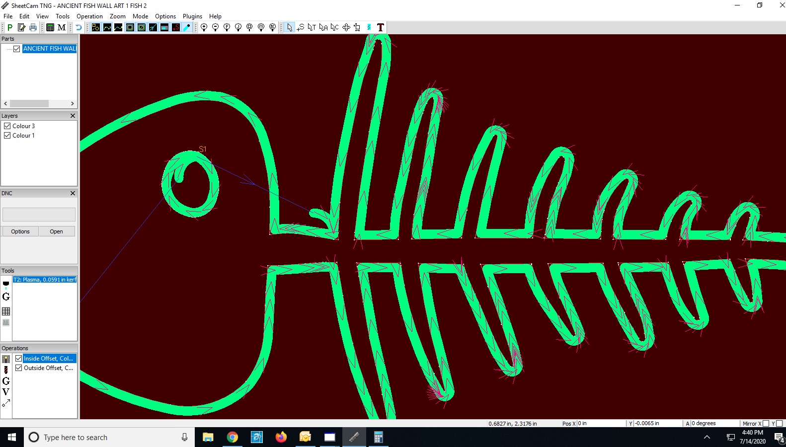
That image shows the problem perfectly. For me it’s not really about the edge of the material as I allow for that. It’s starting your cut from hard stops after bumping the machine to it’s left and bottom hard stop and zeroing it out. Either sheet cam or Fire Control are not acknowledging that the post processing is part of the cutting envelope. It’s very obvious with the image posted by Brownfox the loops are out of the cutting envelope and if you start from hard stops when the cutting gets to the left or bottom loops it will run against the machine limits and throw off the cut by the amount of the Kerf and the size of the loops. My Torchmate software allows for that. It takes into account the whole cutting process and establishes zero/zero. You would never know cutting from the middle of the table but it might bite you cutting multiple pieces and placing them too close not allowing for a long lead in or loops pictured above.
I guess the easiest way to describe it is Sheet cam or Firecontrol are establishing program zero based on the completed dimensions of the part not allowing for the cutting process including kerfs, lead In’s lead outs or loops.
I wish Langmuir would comment on this post.
Maybe you should reference @langmuirsystems in the post and they will…
FireControl doesn’t establish any Zero not programmed. Its likely a SheetCAM issue but potentially a POST issue. Can you post an example program here- we actually are working on a feature (selecting a zero from the corner extents/center of the program) in FireControl that may actually solve this and I’d like to test it out with this particular example.
Unless I’m missing a step in sheet cam any program should do it imported into Firecontrol.
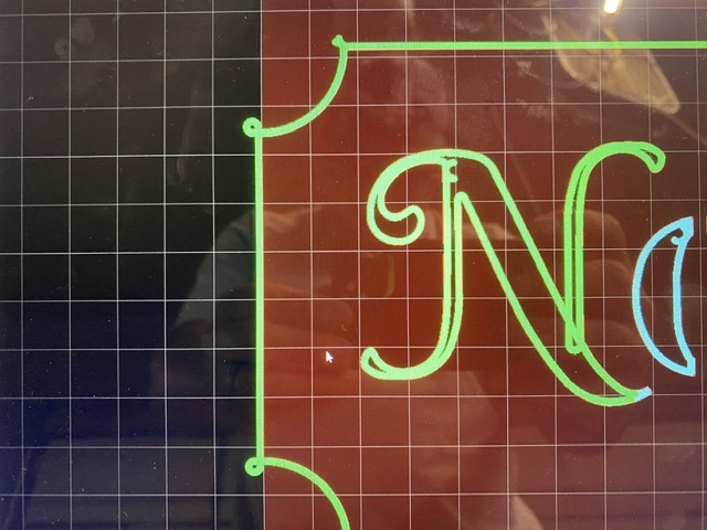
Brownfox’s image shows the issue, the outside left portion of his sign is sitting on the edge of the brown field of cutting area. The outside kerf and loops are outside the cutting field. If you position the Pro hard against the left and bottom stop and try to cut the Kerf and loops will be outside the limits of the machine because they are not being accounted for in the overall cutting parameter which should include lead in, lead out, kerf and loops.
SheetCam doesn’t enforce the ‘cutting area’. It assumes you know where your material is with respect to your hard stops. If you set the edge of your material AT the hard stops and set cutting parameters so the starts go outside your material (ie lead ins with starts on the hardstop edge of the material), SheetCam will generate the correct G-Code to do that. This is how it works. It is not a bug.
1 Like
Yeah I haven’t had any problems cutting. Your statement that it doesn’t enforce the cutting areas makes sense. Like the visualization of the material is just for looks. So it’s not considering x-0 from the design but actually the tool patch, it just doesn’t appear that way.
Let’s just say they give you enough rope to hang yourself… The ‘table’ layout is where you are setting 0,0. It could be at 0.5,0.5 for margin’s sake, or it could be at hard stop. The material position is a, shall we say, ‘convenience’ so you know if you’ve fallen off the edge or not, but doesn’t mean much beyond that.
The cut traces and width shows you where you’ve programmed the tool to TRY to go… if it can’t go there because it crosses a hard stop, it ain’t their problem…
2 Likes
OK, I’m out for now. This thread is going nowhere. I will get my shop reassembled and the Pro back up and running and I will make an example of what I am asking about and revisit this. Who knows maybe I’m full of crap. Wouldn’t be the first time.