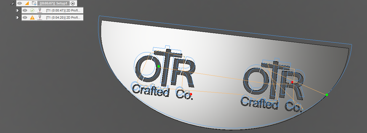
Got a problem with the right half of the larger letters and the left half of the last o.
Tried cutting it several different ways, can get the Large O to cut and lose the small one. Letter R will not cut nomatter what. I have redrawn and resized in inscape and still get this same issue. Usually its a clearance issue or open contour… Please Help.
OTR Gusset v1.f3d (873.8 KB)
I’m not near computer to look at the file but try.
Reduce tolerance to .004
Add smoothing
Remove finishing overlap if applied.
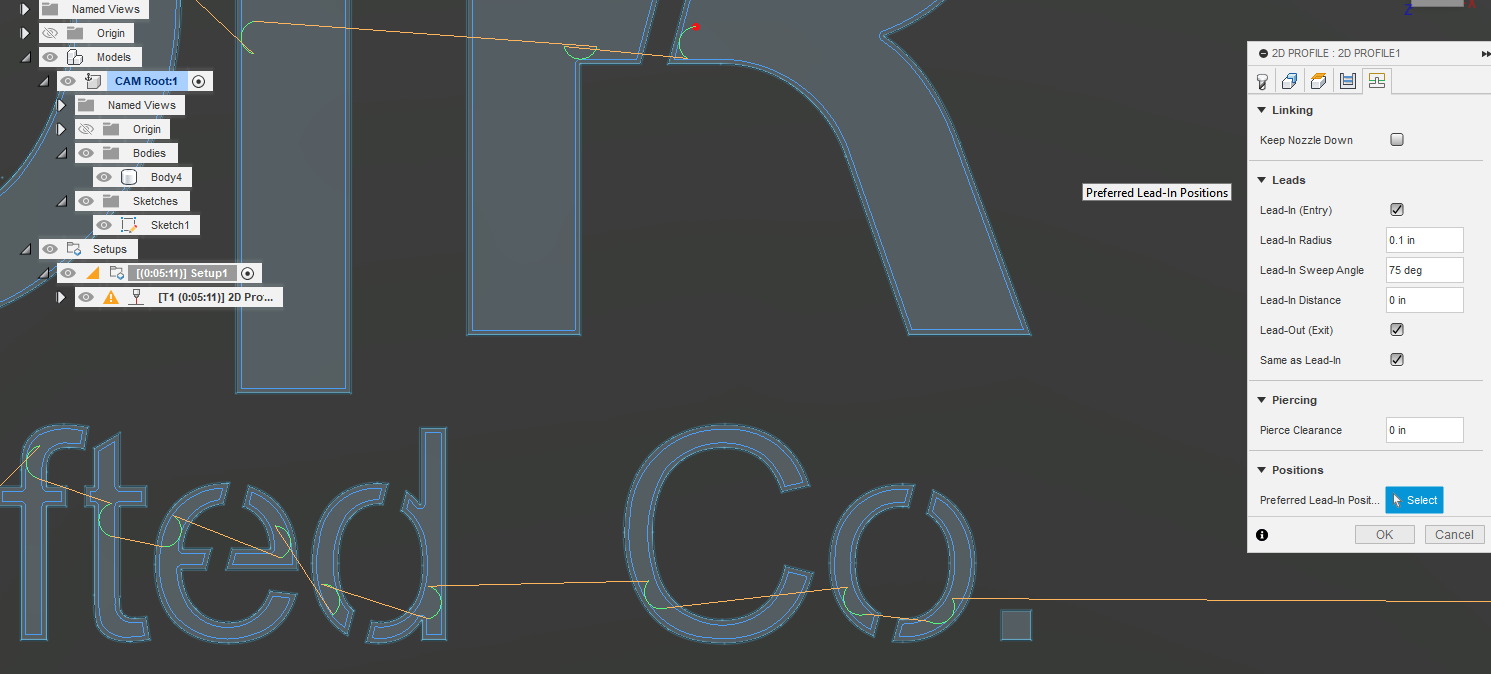
Try adding a preferred leading area to the parts that aren’t generating.
And triple check all your linking constraints ( lead in,leadouts, lead in radius, Pierce clearance, keef, etc) to make sure that they are small enough to fit inside the geometry being cut.
1 Like
I tried what Tin suggested. Those contours were just not taking for some reason. I just added another toolpath and picked those 4 contours and then moved that toolpath into the first position.
OTR Gusset v1Chelan.f3d (873.0 KB)
Note: I really abbreviated the lead-in/lead-out. You could try to increase it and play with the numbers in that fifth tab of the toolpath. You don’t need pierce clearance ever.
1 Like
Thanks for the help, I still dont understand why it was giving me such issues on the large letters. I mean there is 9/16" of clearance in there. I did find that the R wouldn’t cut until I added a bit of lead in RADIUS… I had tried to select that part of the R and cut it on a separate Tool Path, even without lead ins and it wouldn’t take… I also dont know why changing the lead in to be shorter would pick up the tiny o AND DROP THE LARGE O???
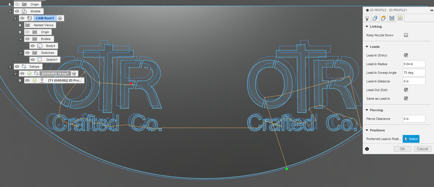
The linking Constraint “Lead-in Sweep Angle” is the issue.
Fusion does not like the tangency of the “Lead-in Sweep Angle” to the geometry being cut.
Change your “Lead-in Sweep Angle” from 75 degs to 60 deg (or other number ) and this will solve the issue.
2 Likes
When I have this type of problem it’s almost always a lead-in dimension problem, or pierce offset. 1. The Pierce offset must be greater than the kerf width.
2. the lead-in must allow for the pierce to happen inside the feature without overlapping the Pierce offset, or kerf width offset. If you want a long lead-in try and angle less than 90 degrees and pick an pierce point at the largest part of the feature.
3 Likes
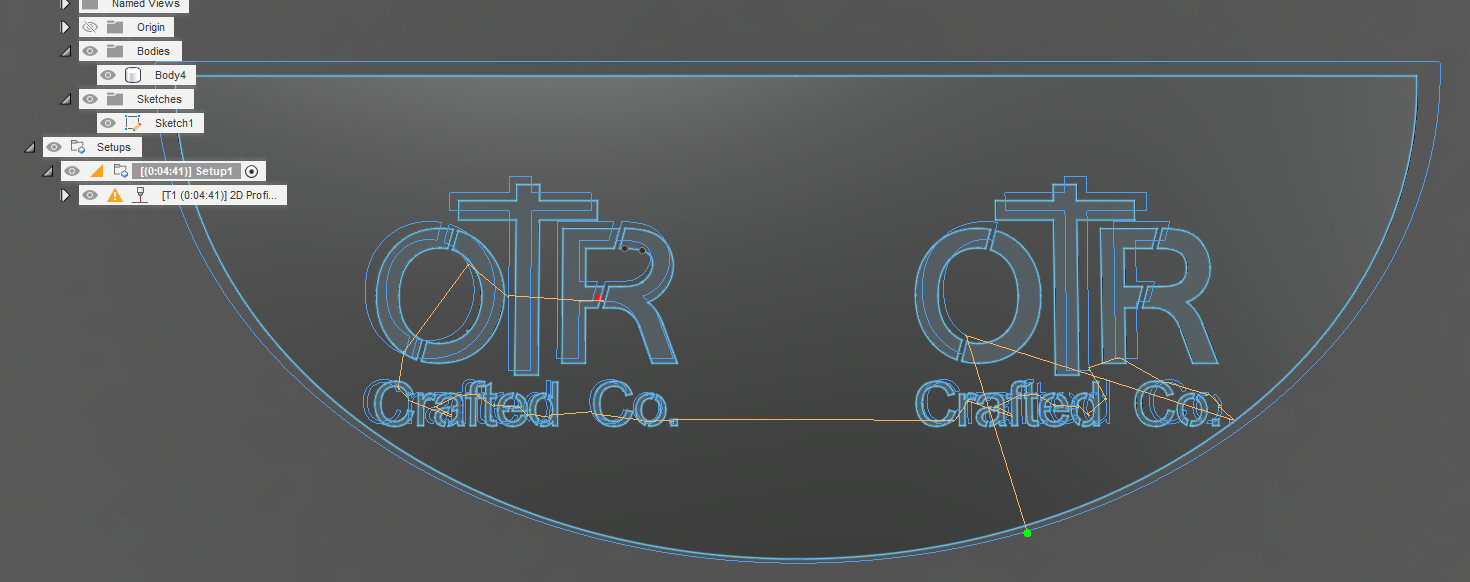
I redrew the right half of the first big “O” and big “R”. Deleted your other body. Extruded a new body and then told Setup and Toolpaths to use the new body. Notice that it now is taking those new contours. I did not “fix” the second ones so you can see how they are still discarded. There is something off with the curved sections. I tried to see but could not find the problem.
OTR Gusset v1Chelan2.f3d (948.0 KB)
Edit: Now Fusion is accepting all contours. Now we have green check marks so it was not the actual drawing?! This particular setting is the largest I could go and still get the periods:
OTR Gusset v1Chelan3.f3d (948.2 KB)
Now the lead-in radius can be changed up to 0.1 inches and fit a decent lead-in/lead-out. Any larger and the smaller letters are going to start griping. Obviously, the periods are not included at this point. So odd. Now that Fusion acknowledges the contours, it is allowing the change. Perhaps you copied the left image to the right and it is now accepting the changes to the right image. But when I CAM’d it that first time it ignored the right image.
Interesting puzzle. Thanks for sharing.
1 Like
Yes, a conundrum indeed… Thanks for All the advice Guys, I will keep these things in my proverbial toolkit. I will cut this one out today. And break it in the morning.
2 Likes