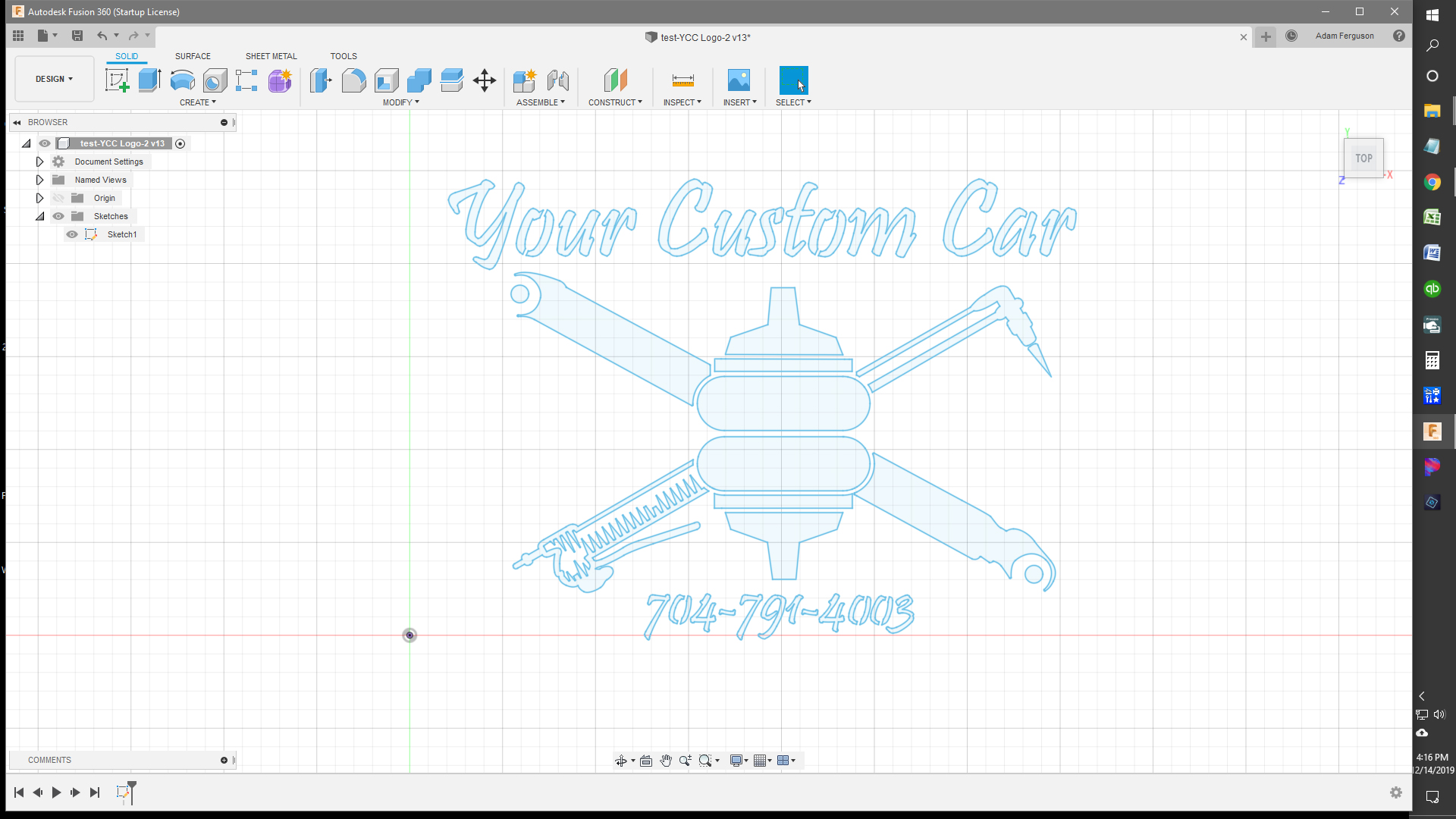
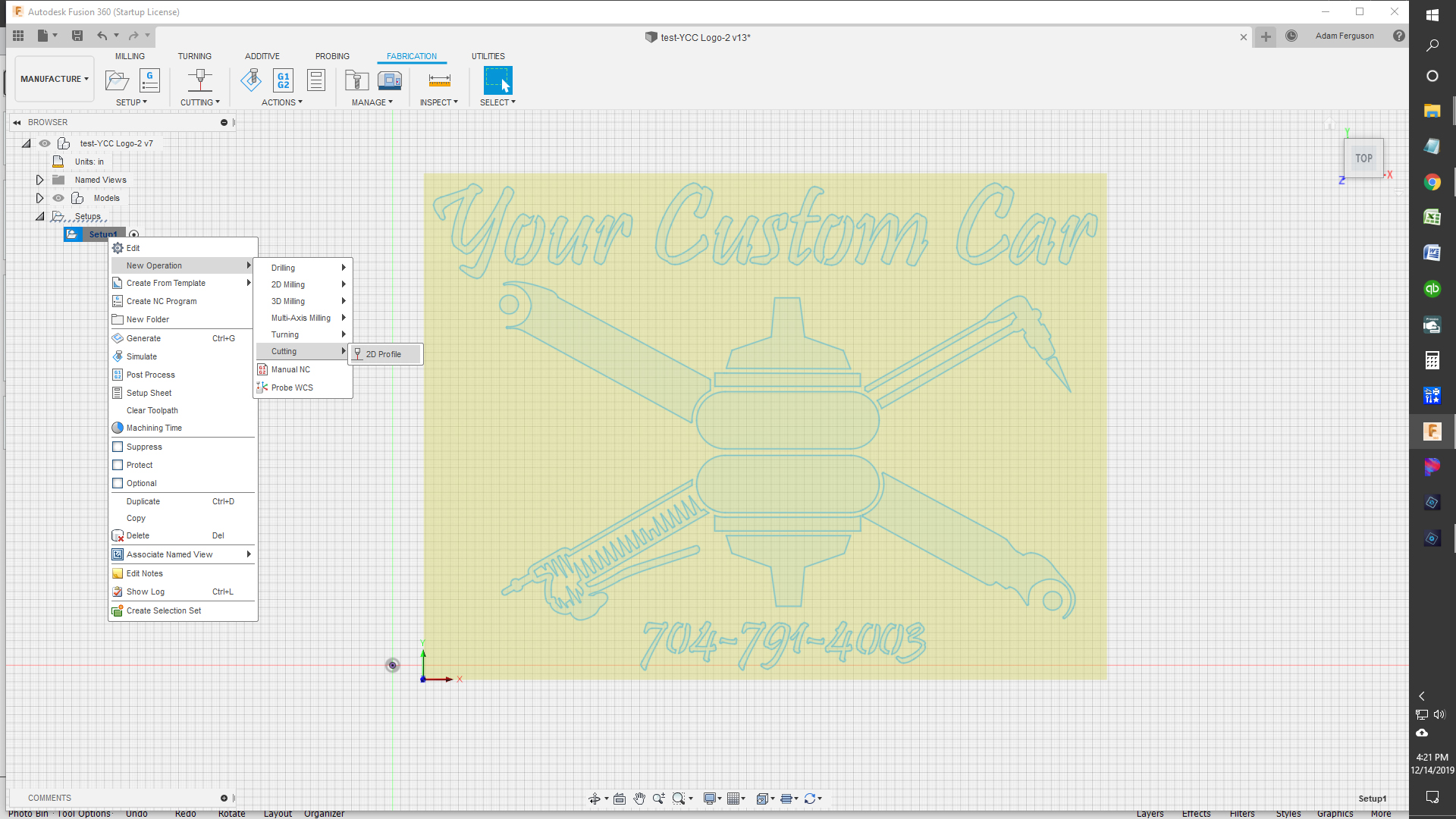
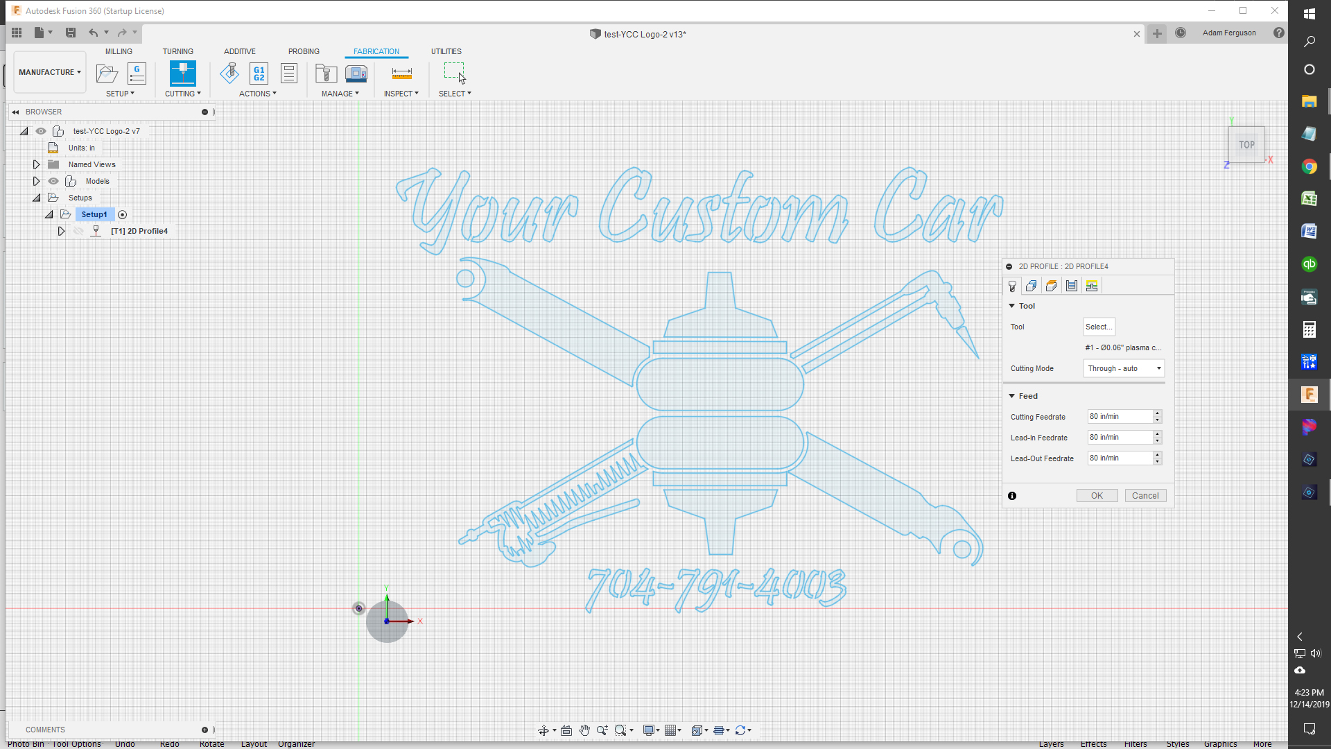
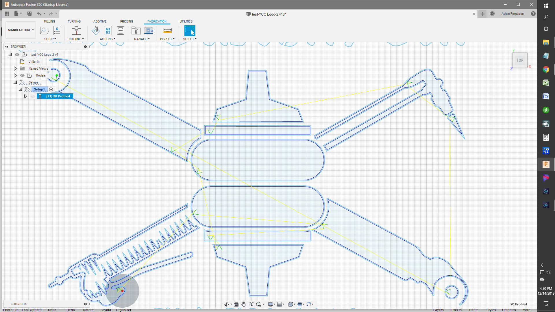
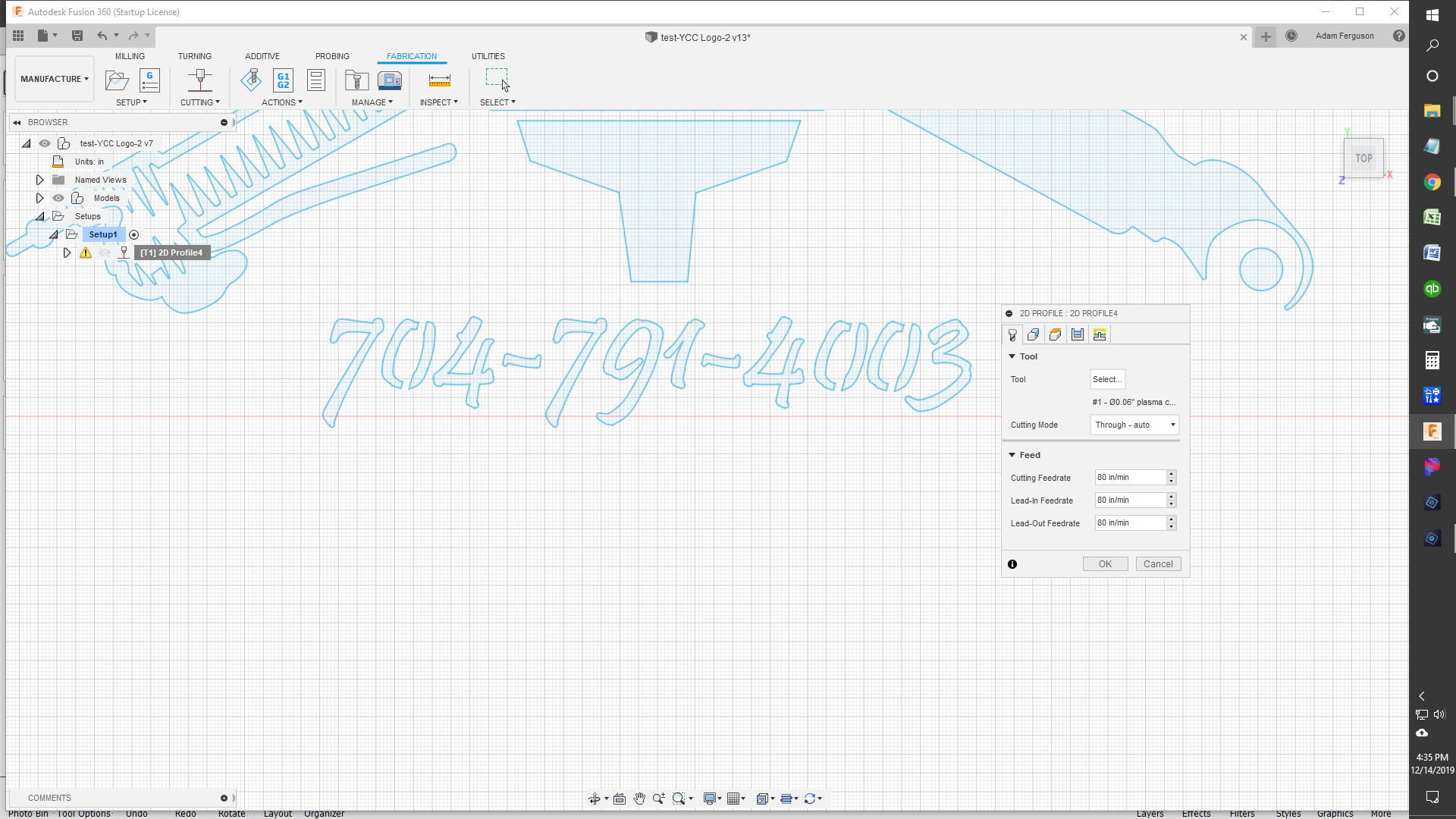
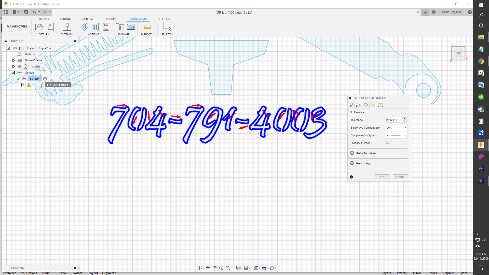
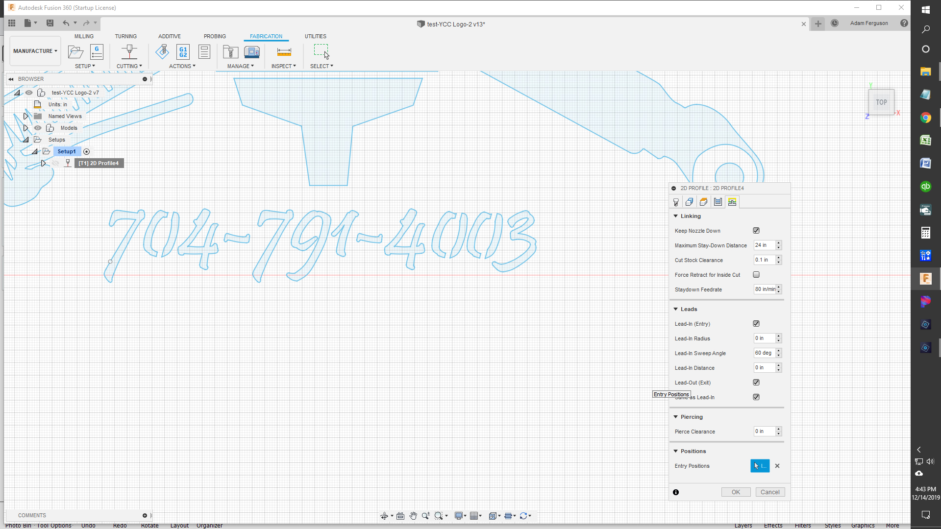
I’m Trying to create a logo that I can cut out of 16 gauge steel on my Crossfire with a Razorweld 45 (.9mm tips). I’ve been at this for 6 straight hours and can’t get the toolpath to complete without errors. The big center image is generating a toolpath just fine at the settings I have (see pic), but the stencil font won’t generate a toolpath without errors unless I completely knock out my lead in radius, lead-in distance, and pierce clearance! I’ve worked on this for far to long to give up, but its driving me crazy that everyone else seems to be able to do fonts. I have tried several different stencil fonts and get similar results. I don’t know where to begin with how to correct it. I’ve included some screen shots to see if anyone sees anything obvious. I appreciate any help!
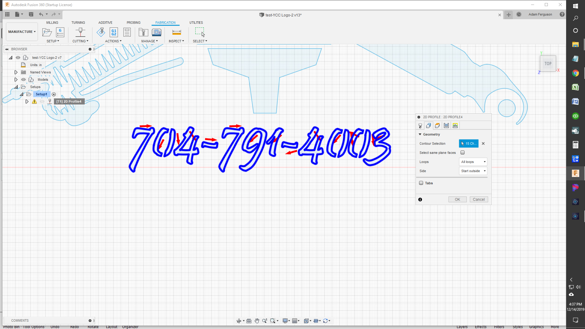
2D Profile for bottom numbers Geometry (How am I suppposed to be able to tell if the arrow is on the correct side?) Finally figured that after I add to the chain, if I click the arrow once, it put it on the inside…
I set mine to .06 lead in radius and .02 lead in lenght.If you want lead ins you have to have room inside you letters and numbers…If it doesn’t fit you have to reduce your lengths or make your font bigger.I just started using sheetcam yesterday and it alot faster to find errors…wish I would have earlier.In sheet cam you set optimal settings for the entire project and if one feature doesn’t work with those settings it will still cut it unlike fusion…I guess fusion will but it will be two different toolpaths.
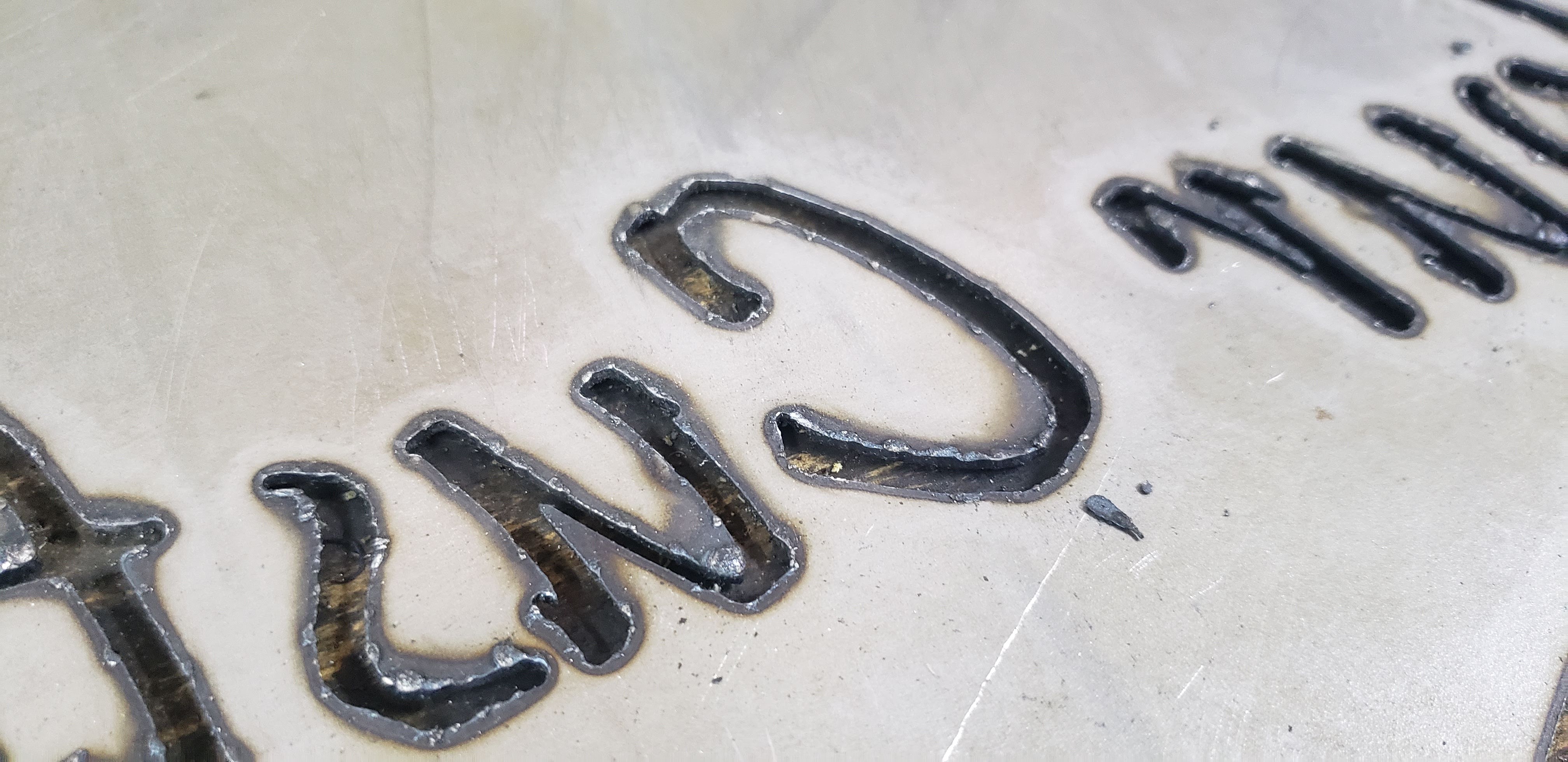
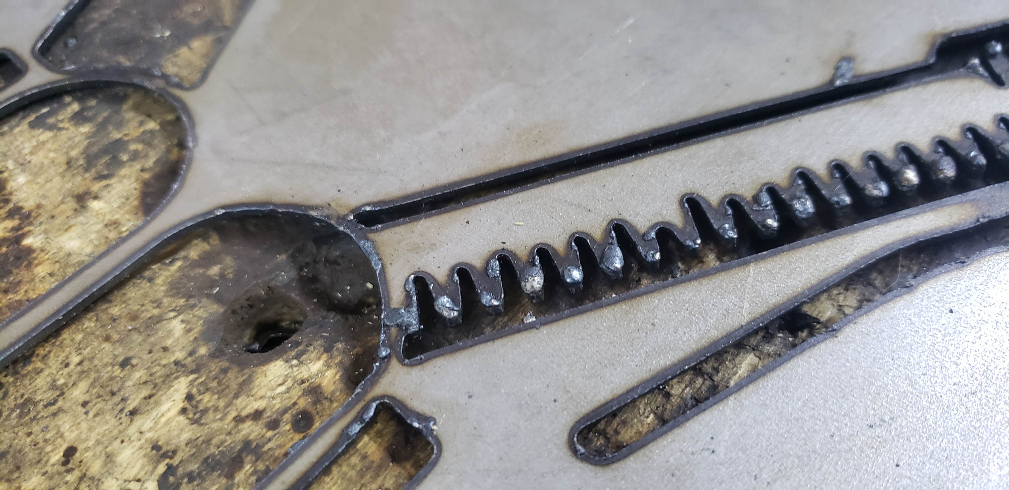
I think after you finish setting up your first path…all the way up to just before post you would just go back to 2d toolpath and create another set up to add to the process tree on the left.Im not certain but that a start…You will have to be ok with divots in your letters if you reduced everything to make it create the toolpath.
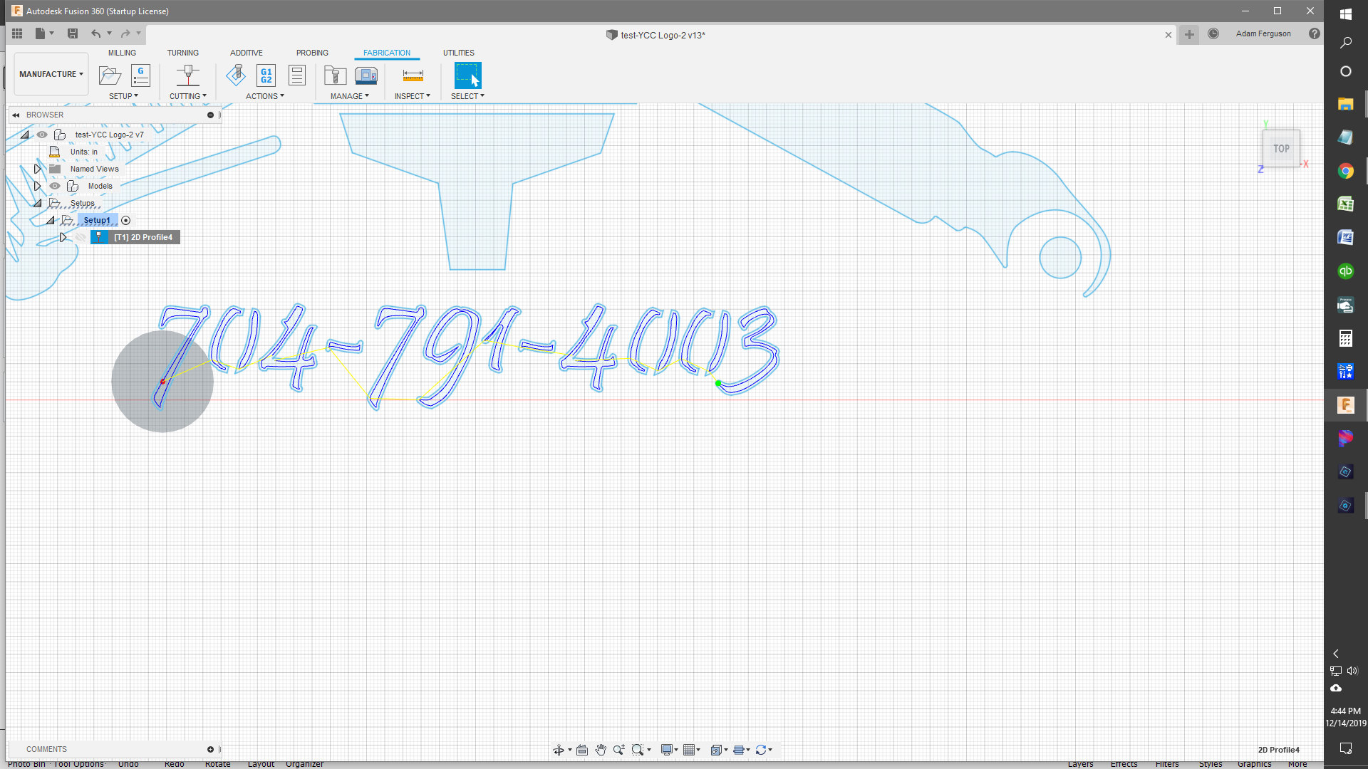
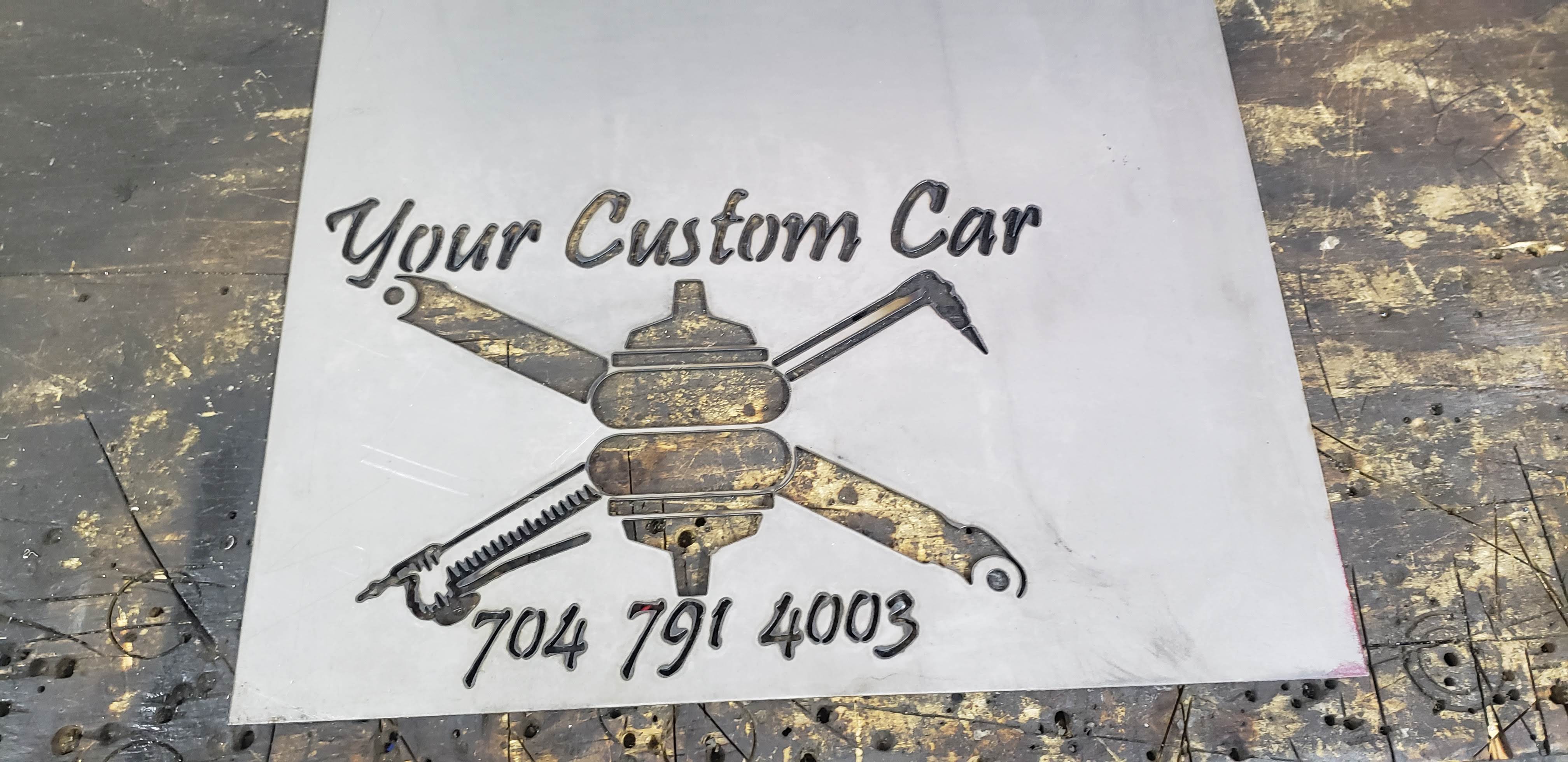
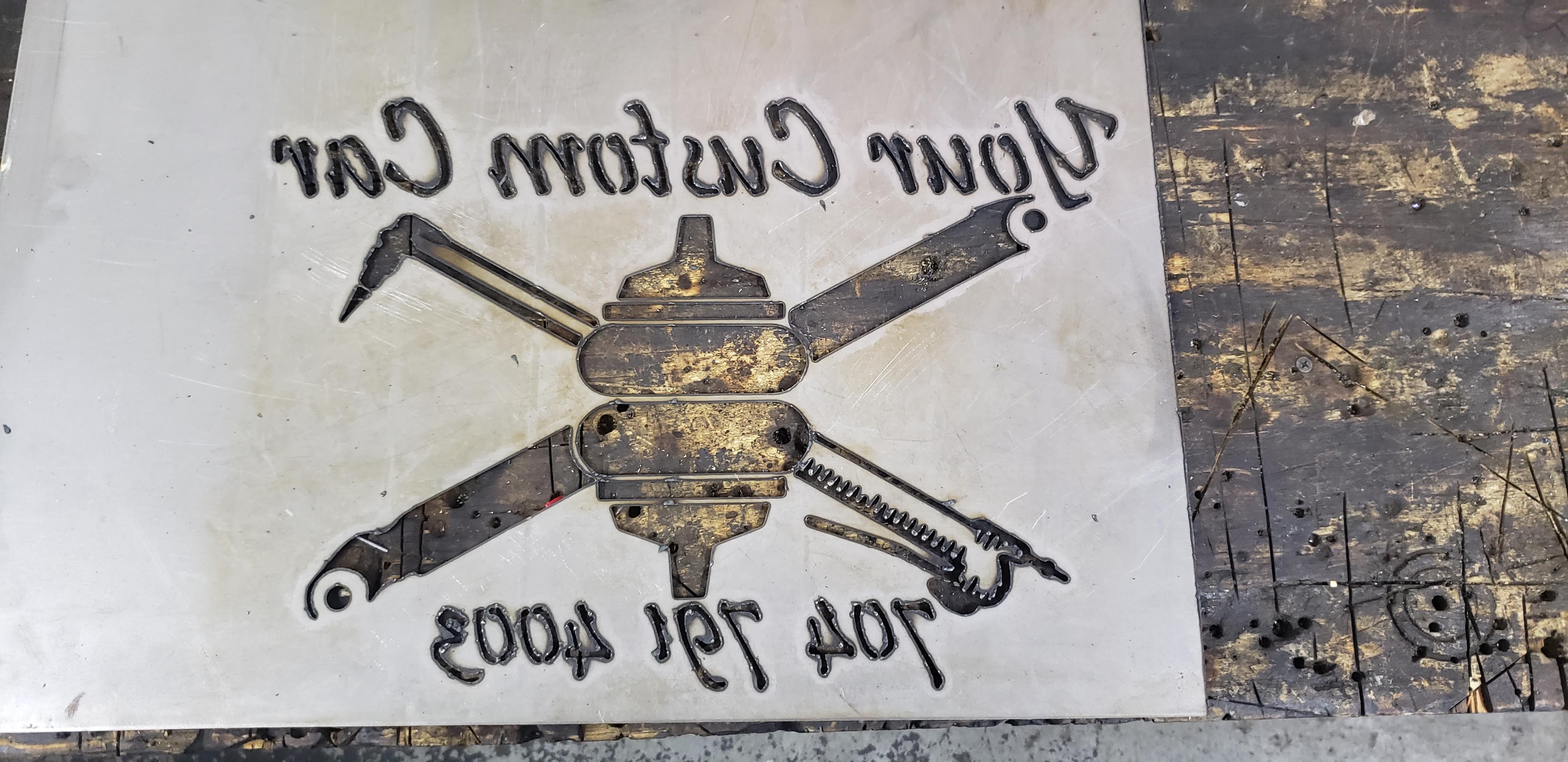
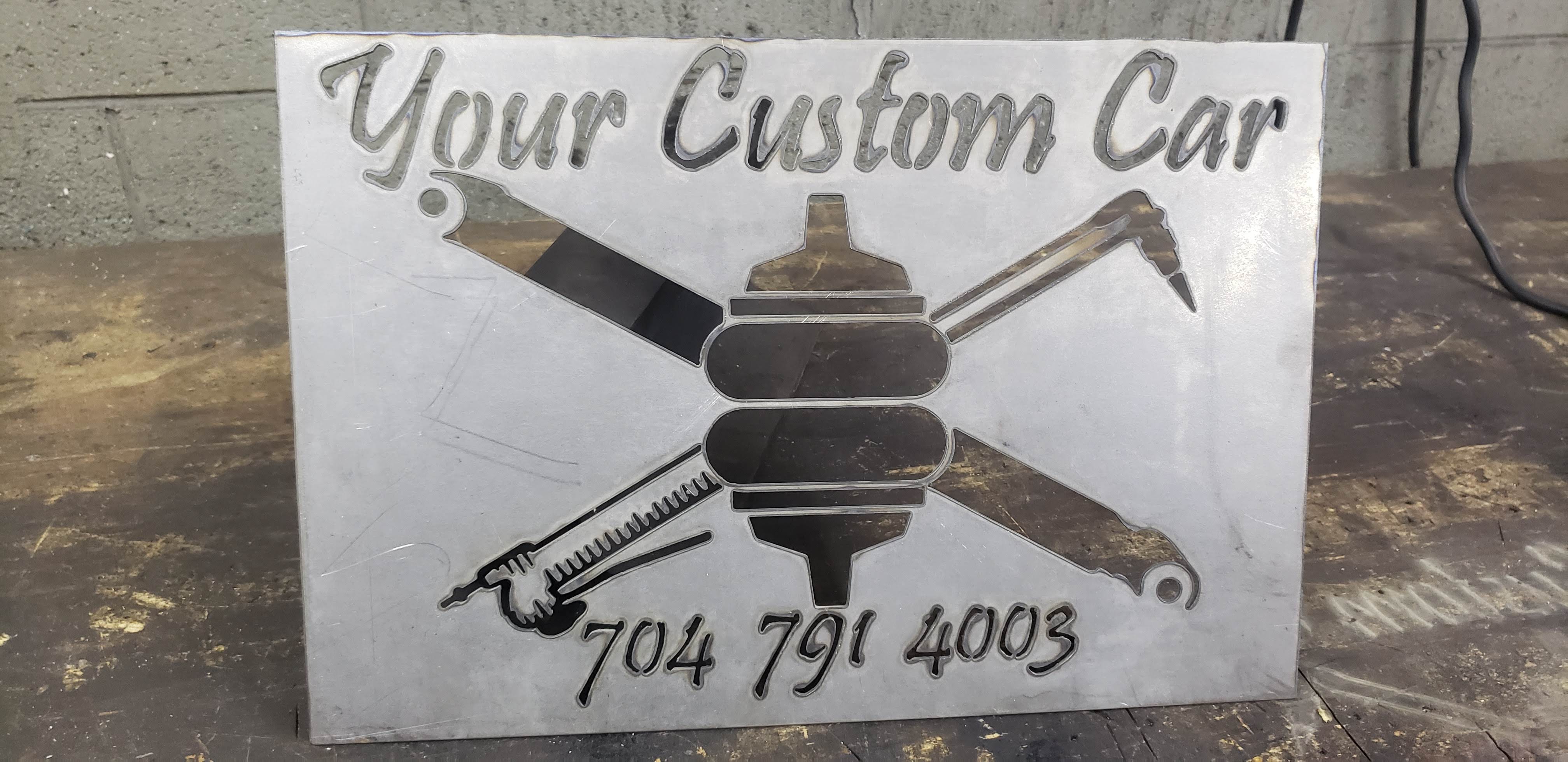
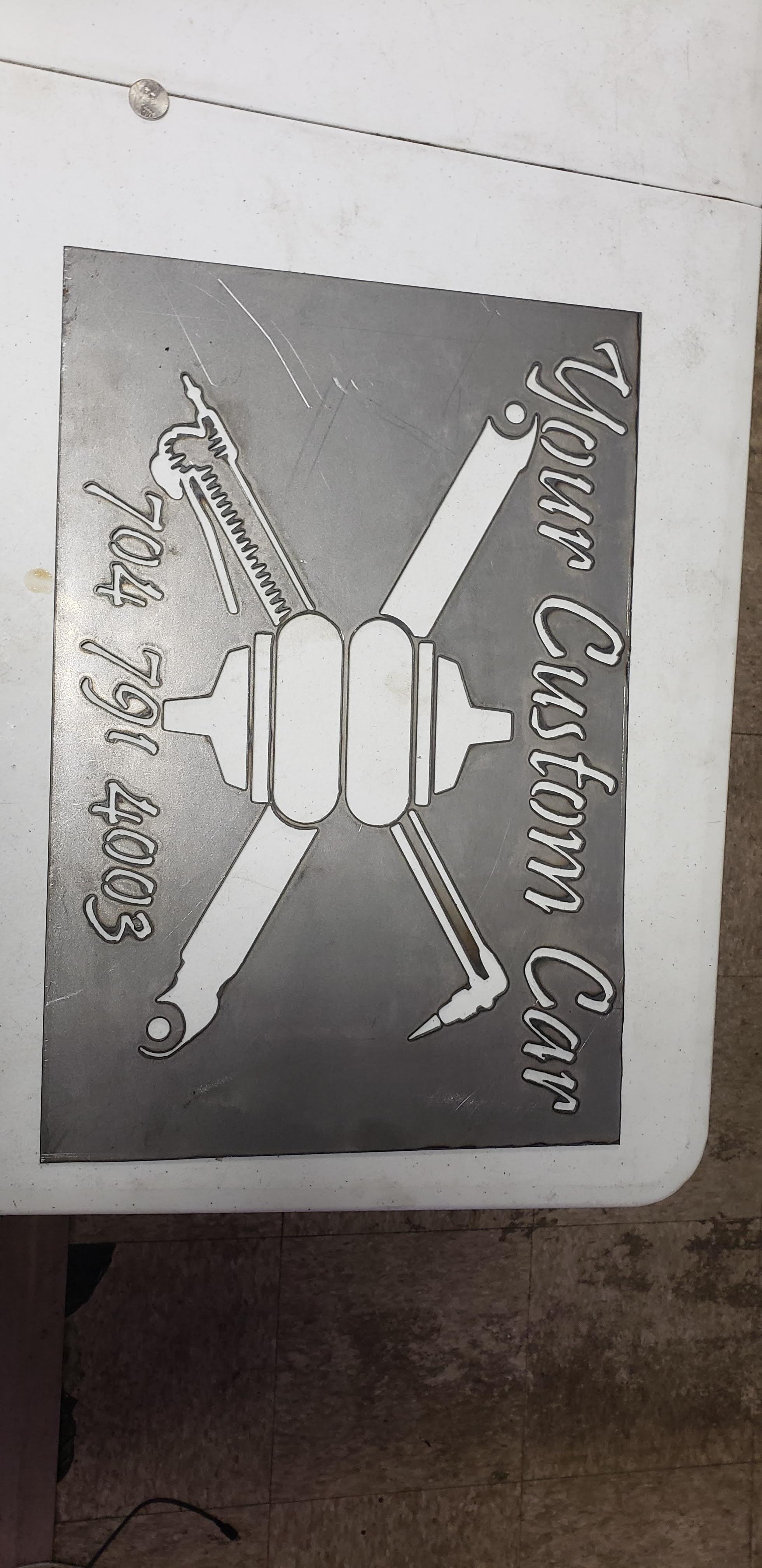
Finally got it worked out! Ended up making font a little bit bigger, adding more entry points, and adjusting lead-ins lead-outs. I didn’t realize how small I must have had the font before until I cut it out. Guess I thought it was bigger than it was since I was using zoom and a giant desktop computer screen… Big thanks to all of the suggestions! I actually got to have fun with my Crossfire today Here are some pics:
Fresh off the Crossfire
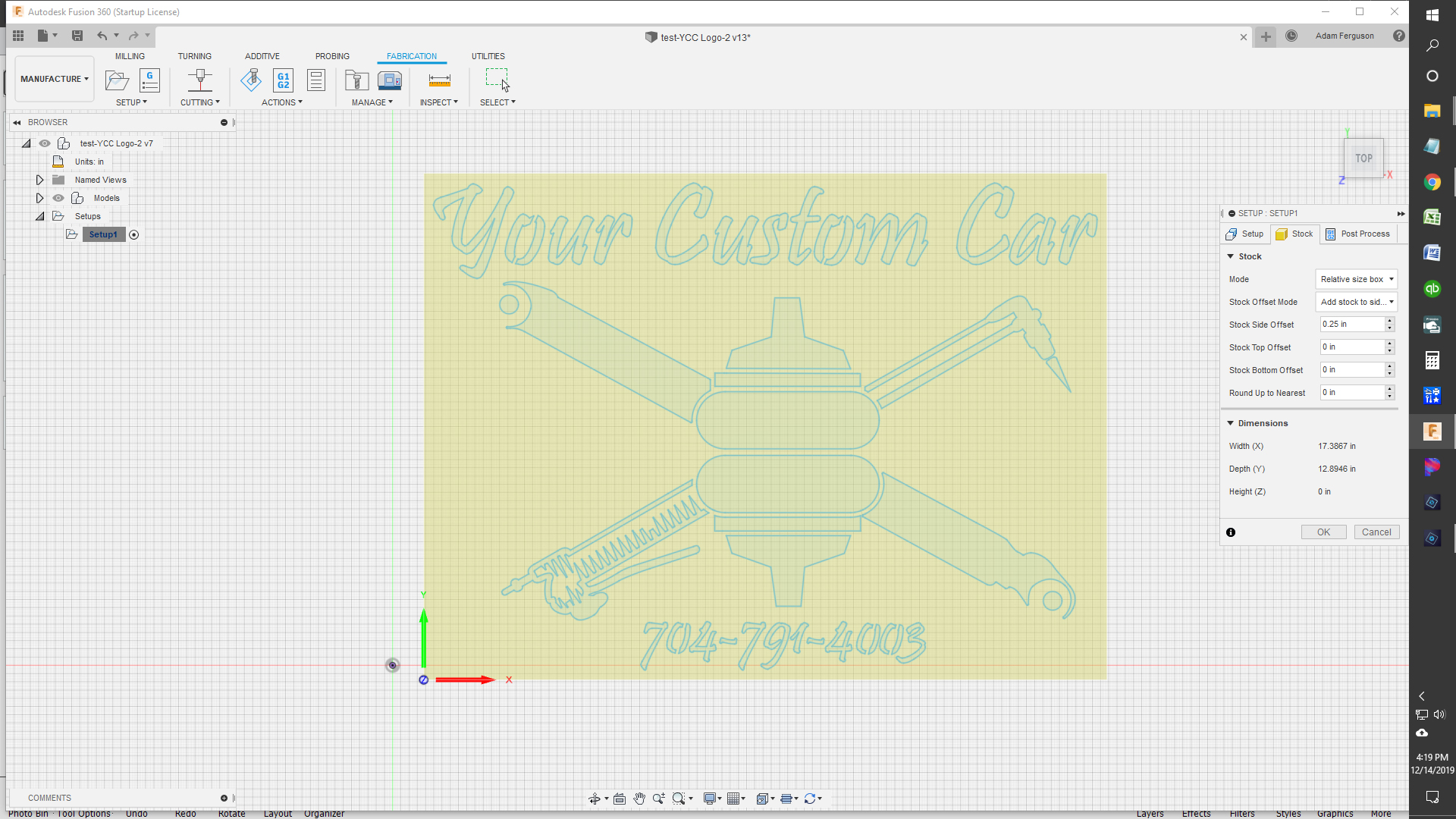
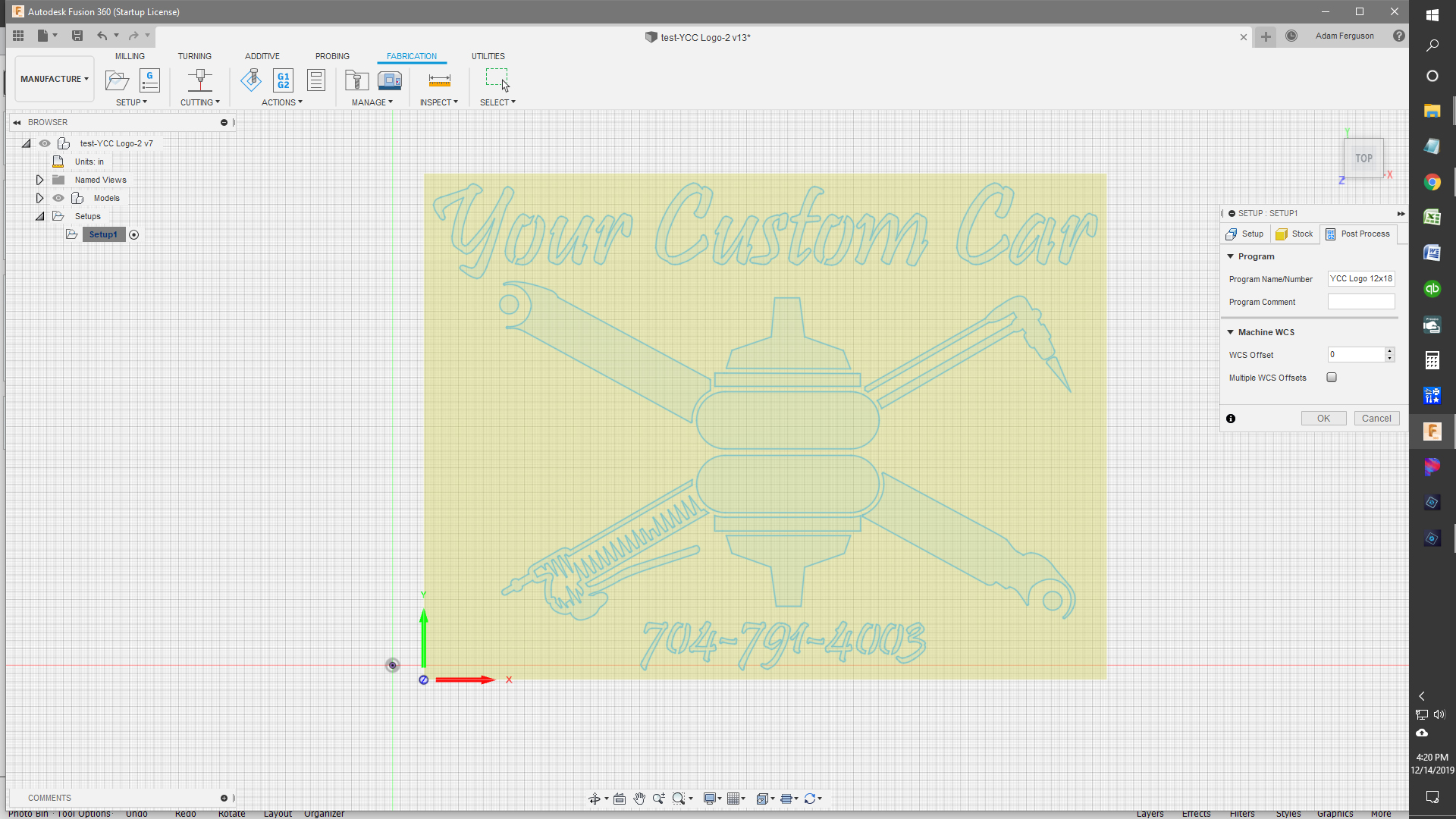
You can have multiple cut profiles under the same setup, the key is to select setup prior to generating g-code. You create additional cut profiles the same way as the first one after the setup. This was particularly useful for smaller cuts and holes that I wanted different settings or feed speeds.
You can also rename the cut profiles and when your running through your g-code you wont have to remember what profile 4 was.
For example…
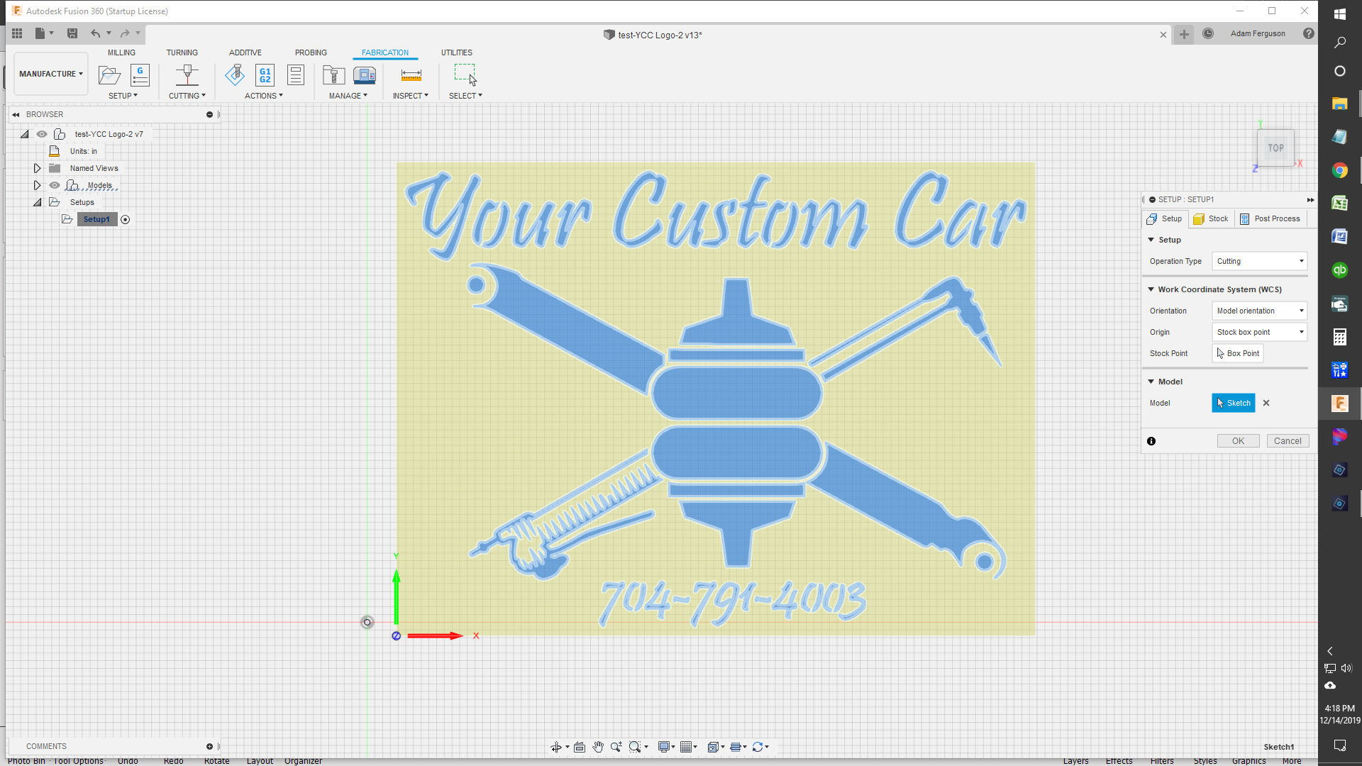
Setup
Your custom Car
Phone number
Oxy-Fuel Torch
Using my example above, if you had Phone number selected and generated code it would only be for the phone number. If you had setup highlighted, it would generate code for all three profiles in the order they are listed.
BTW, the sign looks good, hope this information saves you some time on the next one. I recently made the switch to sheetcam after many frustrating evenings.
Looks good and I’m glad you got it. I always extrude the drawing 0.1" so that I can do a one click toolpath. Then you never have to guess which side of the line the cut is…
I noticed that sometimes when picking cut line on letters that I have to click like 30 different segments of the letter. Then I’ll screw up and have to do it all over again… that takes forever
Will extruding eliminate that too?
You should also install the extension sketch checker…it will show you all your broken lines.Thats why you have to click all the small line segments.Sketch checker will place a dot at every broken line…just trace a line over the broken area then trim out the line segments that dont connect to fix.I tend to fix my broken lines before extruding to make sure I have no issues creating the toolpath.
This might be a stupid question but I was having the same issues with a ton of paths and arrows especially if I’m using a traced image, but when I extrude I’m just getting a solid object. I’m not very fluent with fusion but learning slowly. Say if I extrude a pumpkin I will lose the eyes nose and mouth. Thank you