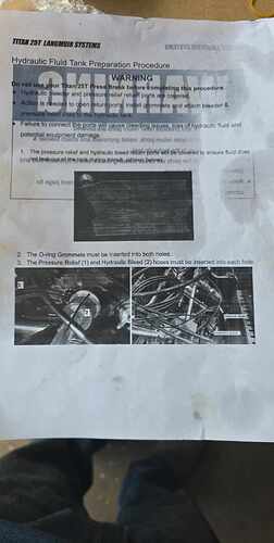
Anyone that’s up and running have a picture of the bleeder and relief lines? My press came with a piece of tape over the tanks holes and a horrible instruction sheet of where they are supposed to go.
Here you go.
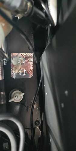
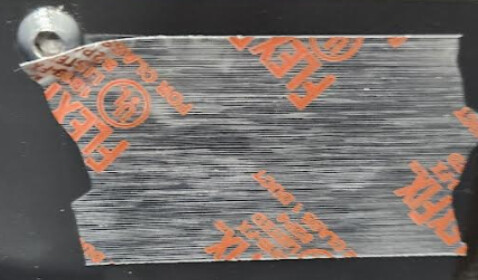
Picture 1 is of the tape covering the fluid tank holes that needs to be removed. The O-rings we ship inside the foot pedal box need to be inserted into those two holes.
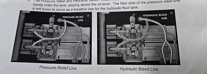
Pictures 2 and 3 are of the two hydraulic fluid lines that need to be inserted into the two holes.
We will be looking into a better way to depict these instructions - the black and white printing run was a short term solution for the new hydraulic fluid tank shipping process.
Thanks Sam was just talking with Danny he got me the pic right after I posted. It’s also confusing thats the one lead is a vent and you sent three grommets. I’d color code the lines or something. Also you might want a hard stop of some kind for the material support arms. People are going to run the linears right off the rails lol.
Thanks, I’ll pass the feedback along. We send three grommets in case one gets damaged or dropped into an annoying to reach area of the enclosure. You only need two. We have a video coming out soon that should better cover this topic.
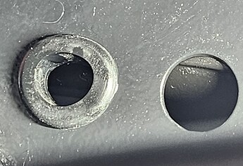
Just got my Titan today and I’m putting it together. When I put in the grommets they are deformed and only go in part way because there is a pipe pushing against the hole. I can get the grommet in for the most part but the bleeder/pressure relief lines barely go in as they immediately hit that pipe. Is this normal? Anyone else have this issue.
It’s hard to tell from the picture, but there is a pipe with a piece of rubber on top (the thin piece going across the top of the hole is the rubber), and it touches the at the top. You can push the thinner rubber piece back a little, but there is still only a mm or two of space before you hit the pipe.
On this picture you show the pressure relief line going to the left and the hydraulic bleed line going to the right. However on the pic included with the Titan it clearly shows the opposite. Which is correct?
It does not matter which hole each line is placed - just as long as both lines go into the tank. It is fine if the lines are barely in the tank since that would put them above the fluid level, which is a good thing.
Mandatory Fluid Tank Prep Guide.pdf (400.5 KB)
Updated Guide to the Hydraulic Lines can be found here.
![]() Thank you for the reply.
Thank you for the reply.
Might I also point out that on the bottom page under “Non-critical” it states that the Expandable Rubber Plug is located in the Foot Pedal Box, mine was not.
Mine was in a baggie zip-tied to some wiring inside the main panel. It was easy enough to see, but for those of us that read thru all the instructions and verify parts before we start assembly it had me thinking it must have been missed during packaging.
I know, I know, what was I doing reading thru the dang instructions before starting assembly… I’m young, haven’t learned to skip those yet…![]()
