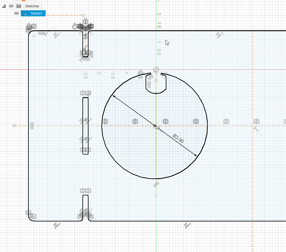
Hi, I tried using the sheet metal bend, but when I choose the option it asks me to select the stationary side, but nothing is selectable, no lines, no shapes etc…
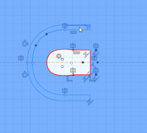
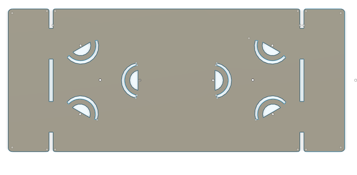
Not sure I have the drawing correct either. These are Sterno candle holders in a plate to prevent them from sliding off. I need tabs that bend up with some relief cuts to help it bend. There will be 4 of these tabs, I just have one created for now.
Any tips on how to draw this and make bendable tabs?
Thank you! I’ve done your tutorial in the past, I wasn’t sure if I could just draw something and bend it up, but looks like you have to go through the entire process.
I should be able to draw a kerf cut in the drawing, and bend it ?
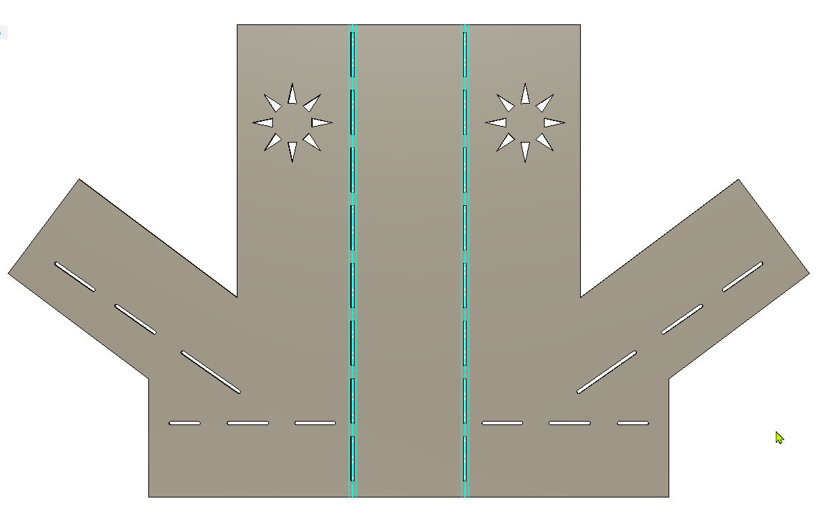
You are correct. The way you have it drawn, you already have the tabs so you can just cut it out. I thought you wanted to see it fold up in Fusion by following the Sheet metal rules.
If you don’t have a reason to join up several parts and simply need tabs in your plate of metal, you did fine.
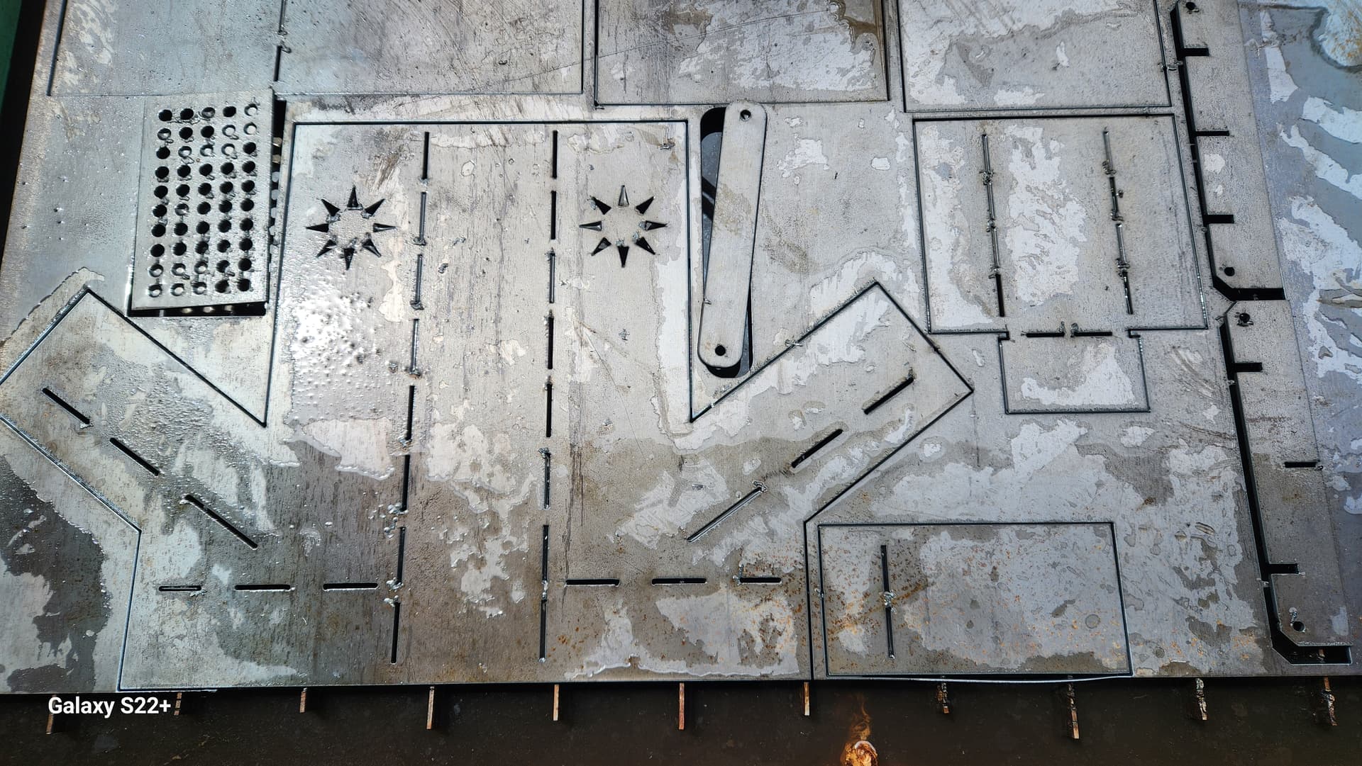
In this example, I wanted to cut out the parts with the least amount of fitting mistakes so I used sheet metal because the sheet metal function applies the K-factor for how the metal will stretch for a given type and thickness of steel. If you are just guessing for how the metal reacts, once it is bent, you are likely to be ‘off’ with your pieces.
I am not sure what you are trying to do with that illustration. You might be making it more complicated than it needs to be. If you are simply making a cut that bends out, such as the middle part of your drawing, I am not sure that the sheet metal aspects apply.
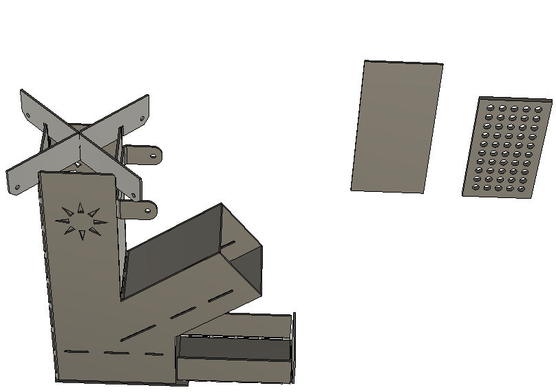
I am not very clever in the sheet metal environment. Others will weigh in but you will need to give more detail of what you are trying to do. Basically, I draw in in 3D view when I am in Sheet metal and then convert to sheet metal and then unfold. You seem to be drawing in the 2D world and trying to make it 3D.
Bending a flat design is one thing. It’s another to create a single face, create flanges, and flat pattern the design to get accurate length pieces for placing holes/slots in their respective locations.
I would suggest looking into using the sheet metal function in designing a part.