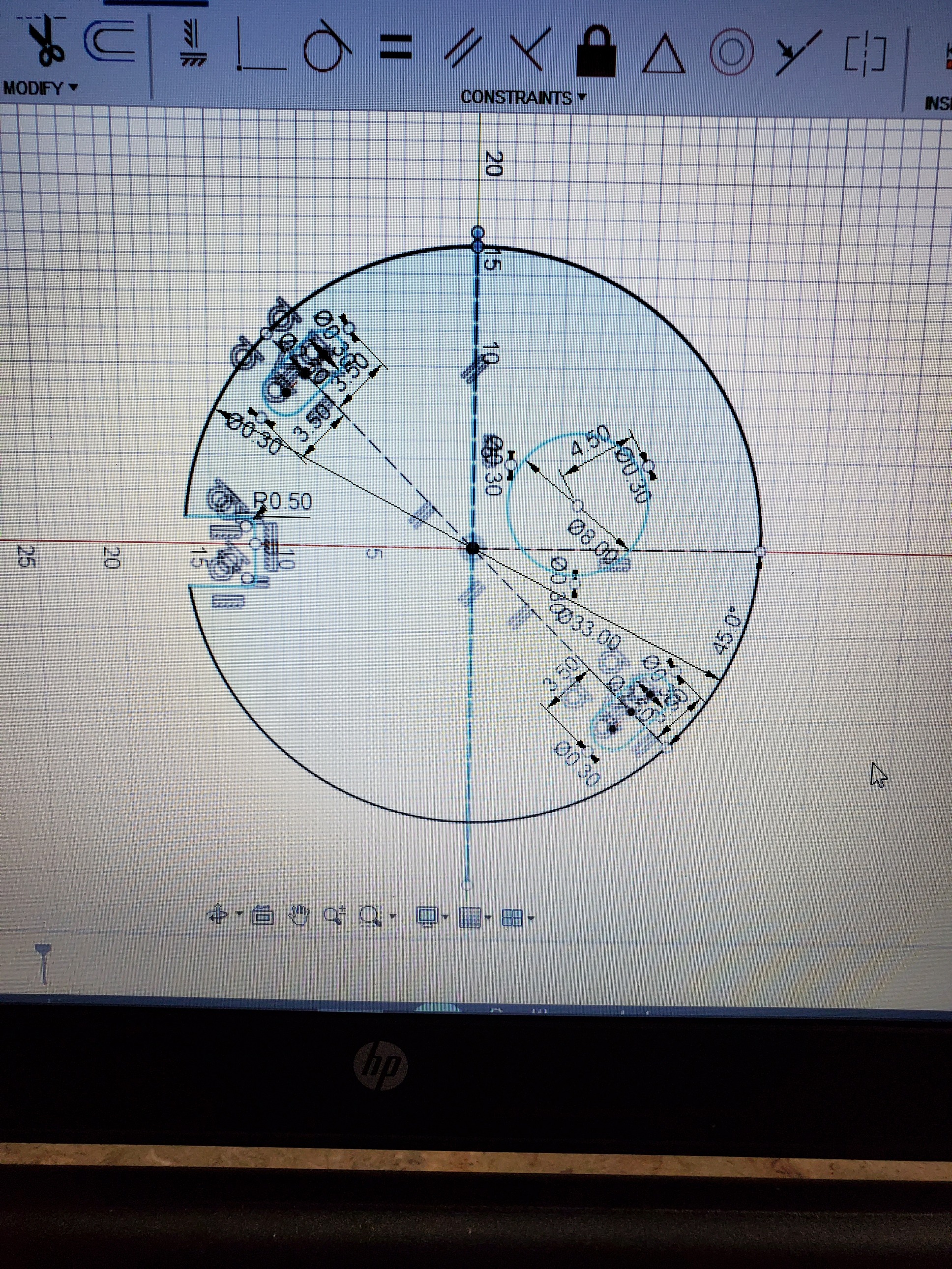
This is an easy way to index cuts in Fusion. I don’t use Fusion for post process so I can’t help you there but I’ll explain how I do it in Sheetcam. I cut this 33" circle last week. Draw a construction line where you want the break. Select all lines of the sketch and the construction line and copy them.
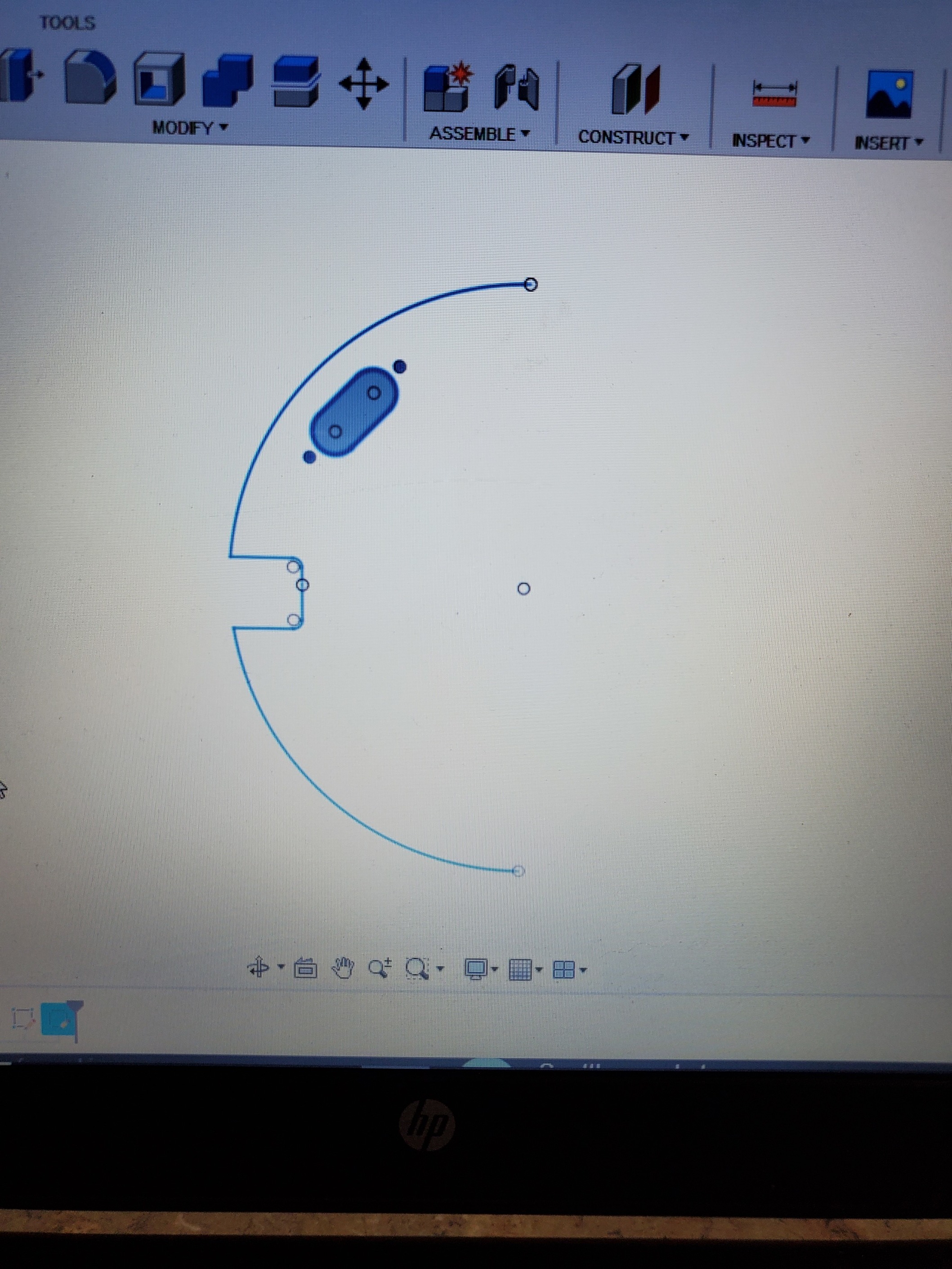
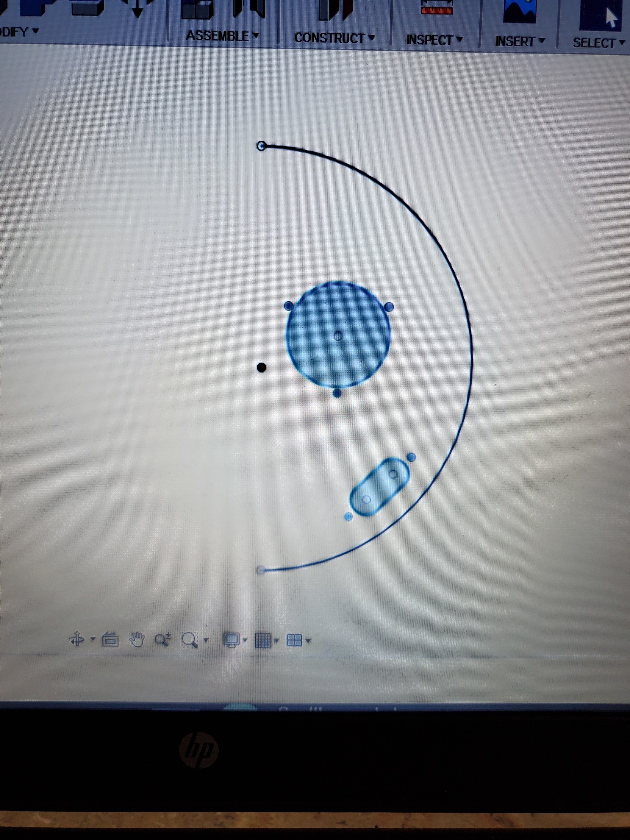
Create a new sketch and paste the contents of the original sketch into the new one. You should have two identical sketches. Delete everything on the right side of the construction line on the first sketch using the trim tool and then delete the construction line. Do the same to the second sketch but the opposite side.
Save each sketch as a DXF as side 1 and side 2 or whatever you want to call them.
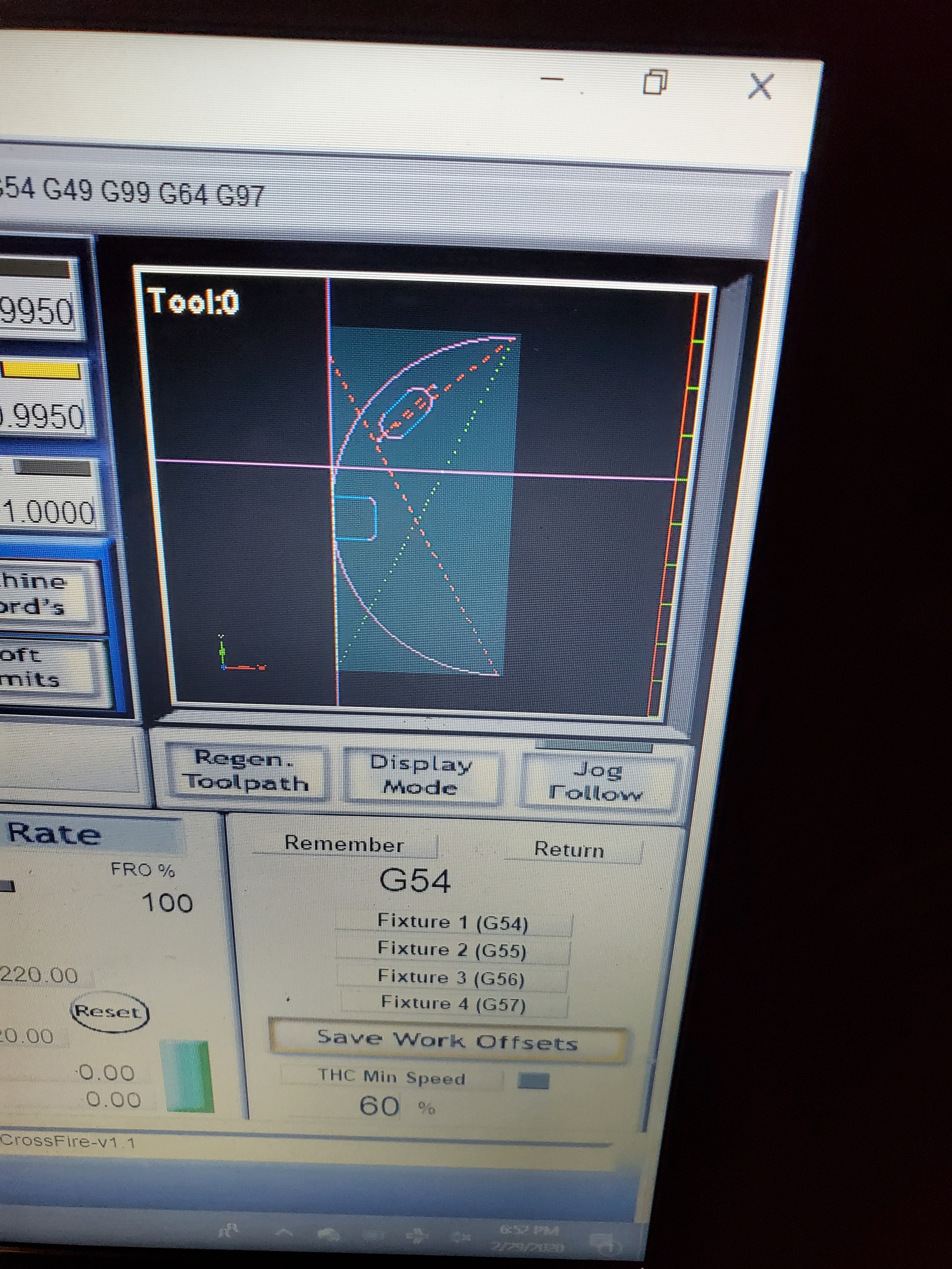
I didn’t grab pictures of Sheetcam but there are only a couple things you need to do differently when generating the cut paths. When importing the drawing, select “offset open contours.” Generate cut paths for the normal, complete contours (my complete circles and ovals) on their own layer. When generating a cut path for the open contour (the incomplete, half circle in my case) add it to it’s own new layer and select no lead in/out and outside offset. For the second half, you’re going to need to use the rotate function in the bottom right hand corner and rotate the second image 180 degrees if it’s a circle like mine. If you’re simply sliding your work pieces down the Y axis and not rotating it, do not rotate it in Sheetcam. You should have two G-code files now, one for each half.
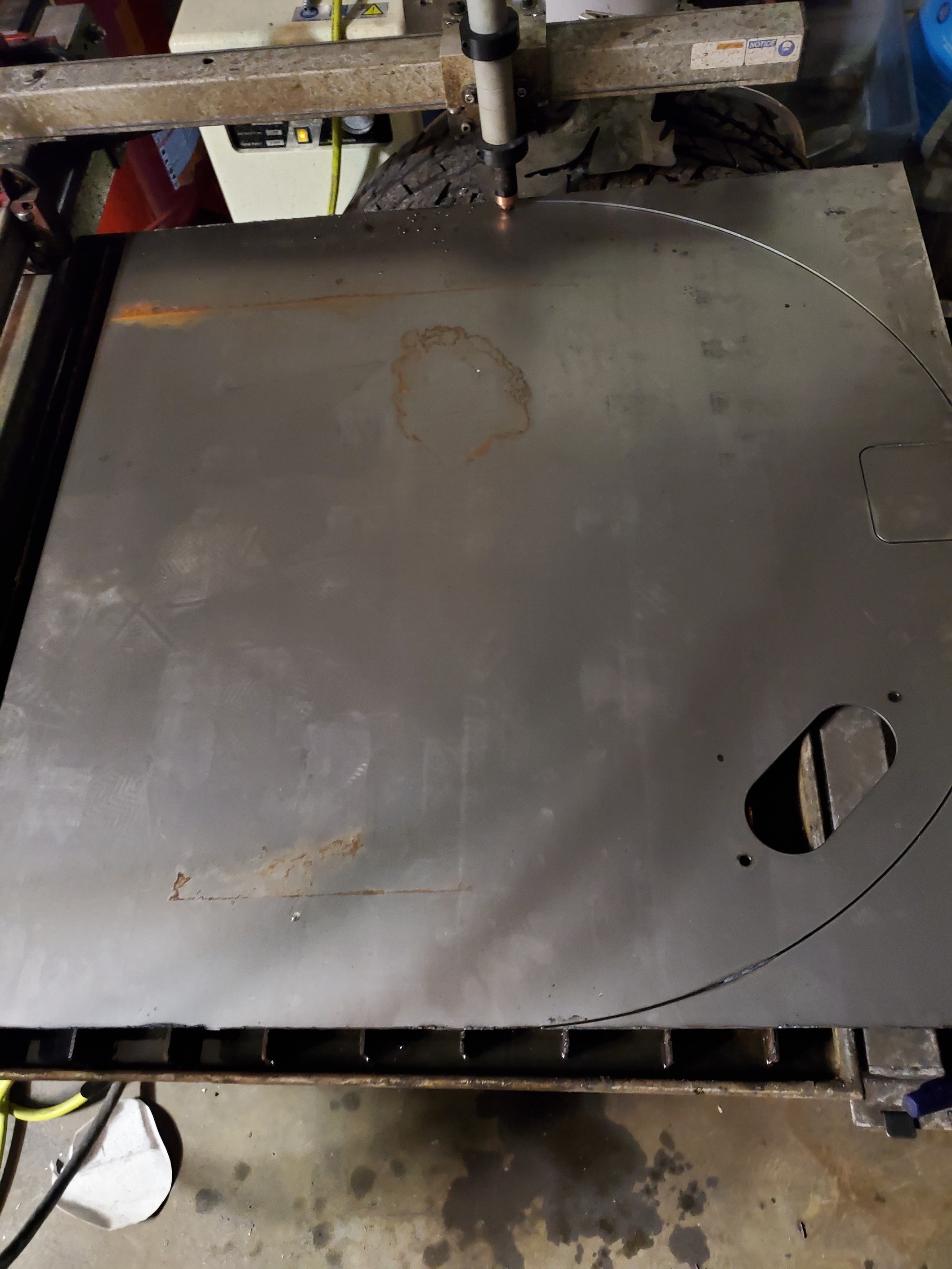
In Mach 3, cut the first half normally.
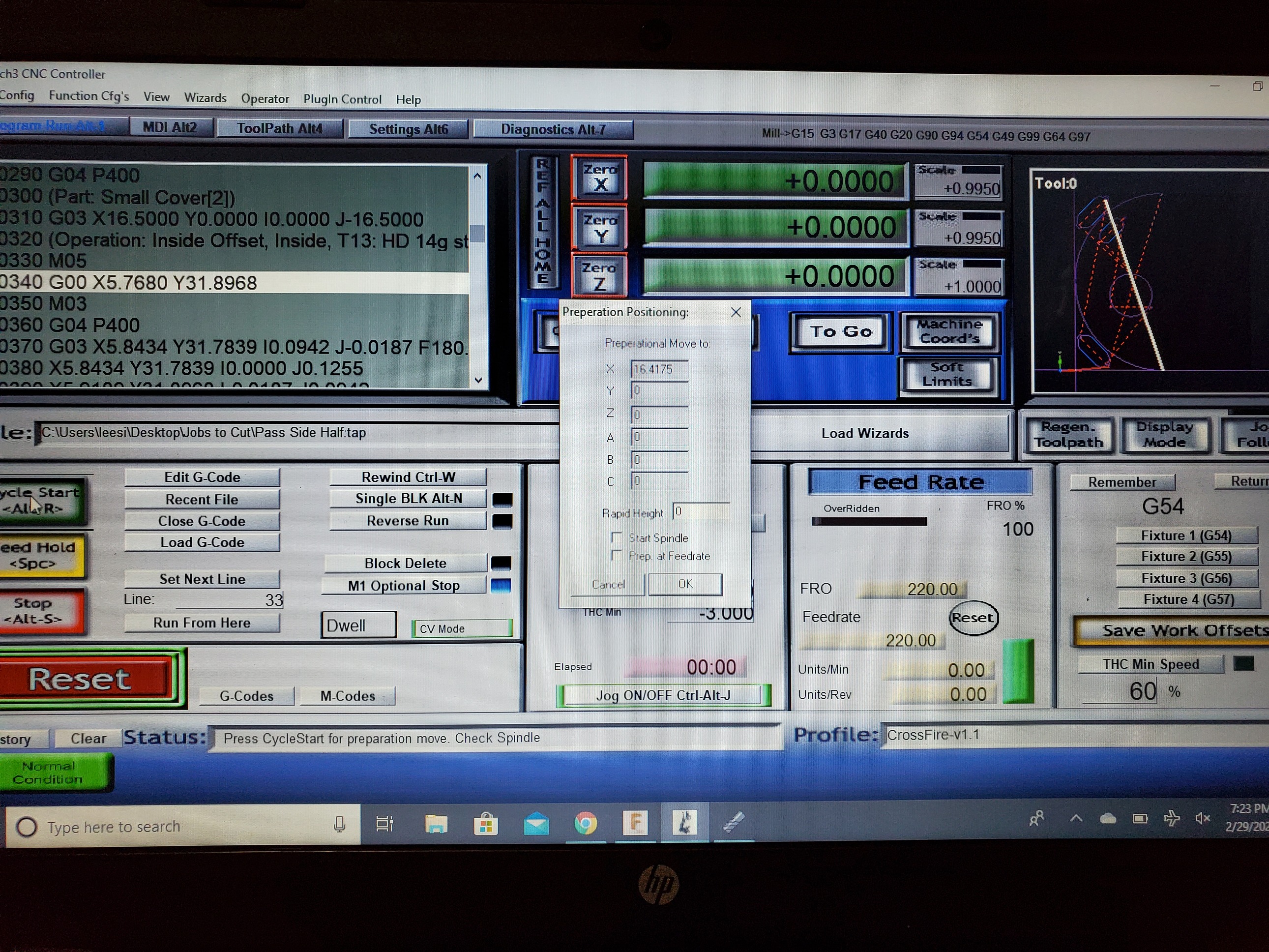
Afterwards, load the second g-code and use the “run from here” function to move the torch to the beginning of the second half of the incomplete circle. (do not check the “start spindle” box!)
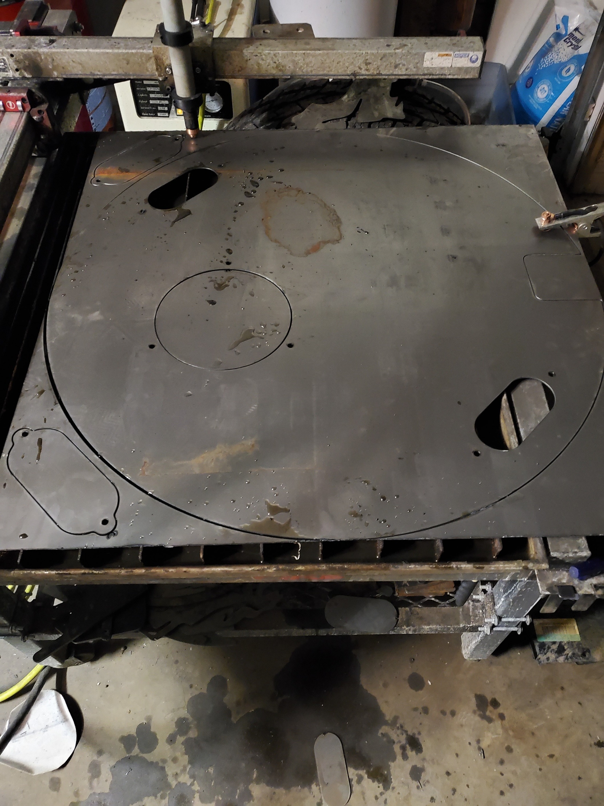
With the torch positioned exactly where it will start the second half of your circle, line the work up where the last cut left off. Use the “run from here” function again and find the END of that half circle (or whatever you’re indexing) and align the end of the first cut to the torch position. I’ve rotated my metal 180 degrees here, aligned the first half of the circle with the start and finish of the second half of the circle, and it’s ready to cut the second g code file.
Run the second cut.
And I’ve got my new floor for my Jeep with access panels. Mine lined up perfect. Even if it were off by a tenth of an inch, it wouldn’t have mattered for my application as I could have just used a flap disk to smooth it out where the lines didn’t quite come together. But it might matter to you if it were a precise art file so maybe take a little extra time lining it up top on bottom, left to right, whatever you’re doing. I’ve done this successfully on a large 33" monogrammed letter. It’ll work on more than a simple circle.
Hopefully this made sense, I’ll try to clarify if not. Just ask.