The code is designed to analyze your source file and look for ‘G0 Z1’ which is at the end of every cut loop. It counts the number of instances of ‘G0 Z1’ and returns that as the number of cuts in your source file.
Then it creates a new file and adds the additional commands to each cut loop based on the options you select.
However if your file does not have ‘G0 Z1’ in the loops then it will not work. All of the files I have generated have G0 Z1 in each cut loop so I’m not sure why it’s not working for you.
FYI below is a snippet of the code that analyses your source file:
Dim stringReader As String
cutcount = 0
While fileReader.EndOfStream = False
stringReader = fileReader.ReadLine()
If stringReader.Contains(“G0 Z1”) Then
cutcount += 1
End If
End While
Label5.Text = "The Total Number of Cuts in the Source File is " & cutcount
With fire control closed, open the serial port with putty at 115200. Type $$ to see all the settings.
The Grbl setting that controls the maximum rapid speed (G0) is $110 for the X-axis, $111 for the Y-axis, and $112 for the Z-axis, which define the maximum rate in mm/min for each respective axis.
These settings determine the upper limit for rapid movements, which are executed using the G0 command.
Change $110 and $111 to slow x and y rapids.
Syntax $110=1000.0 where 1000.0 is the speed you want. Don’t make any mistakes, backspace is not supported.
If successful, you’ll see OK, otherwise some error code. Then change y $111. You can always change these back. Changes are stored in EEPROM and stay in machine.
Save all the controller settings somewhere in case you need to restore.
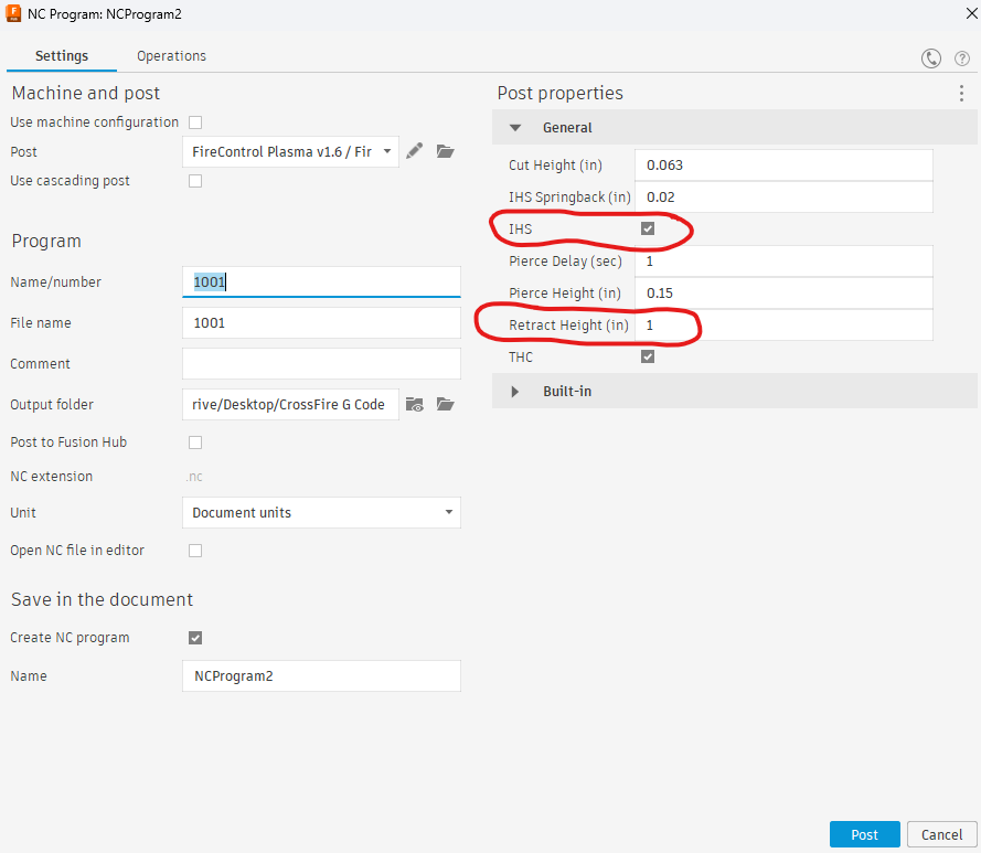
Ah. So it looks like you don’t use IHS (Initial Heigh Sense) in your Fusion360 Post setup.
I’m using a CrossFire Pro with IHS. At the end of each cut, my machine retracts to 1 inch above the work piece (Z=1) and then touches the piece on the subsequent cut to reset the cut height for each cut. This is an upgrade over the original Crossfire as I understand it and produces better results if the material to be cut is warped etc.
I exploited the ‘G0Z1’ at the end of each cut to write all the code for my program.
If you are not using IHS with a retract height of 1 inch, then my program won’t work for you.
Here’s a screenshot of my Post settings in Fusion360: