Hi Guys
Anyone work out a good method of locking a datum corner into the water tray? The connection splice bent ones not any floating drop in supports. Goal is to will provide a repeatable X-Y position to drop flat bars to cut interior profiles and holes and some potentially use it for smaller square or rectangle tubes? I have some thoughts and ideally it would have some small adjustments that can be locked. We just added splash shields to our XR machine and they prohibit attaching the fasteners to the perimeter of the drip tray.
Thoughts were to home the machine then do 1" jog offsets to get us to the/ datum corner VS using visual. Burn some holes and caliper check , then dial in any corrections. To repeat drop back in to some same features in water tray.
I have mine set up but they bolt through the top of the water tray which you need to avoid.
I am curious to see what peoples ideas are.
I like the splash guards, are they working well?
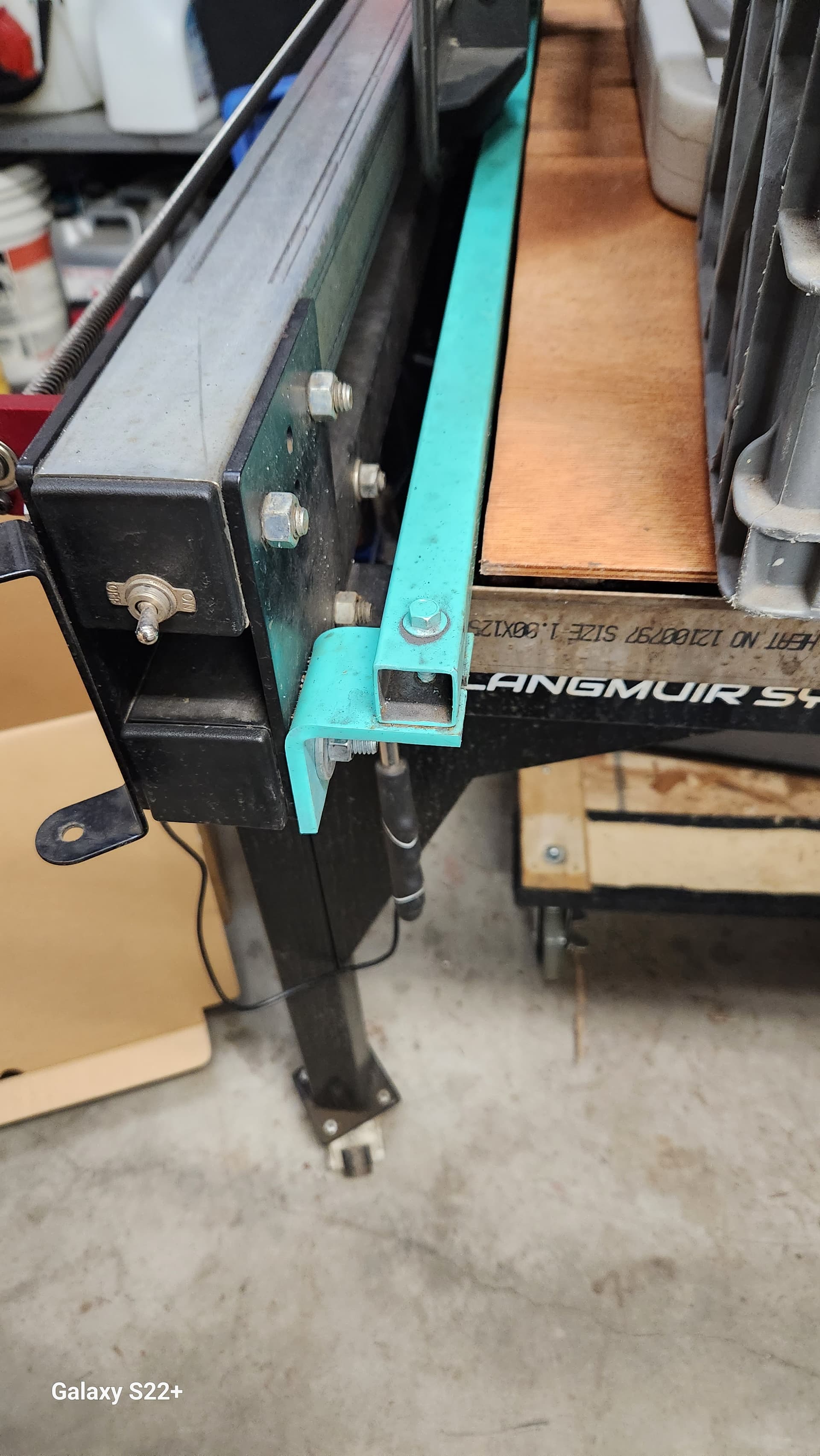
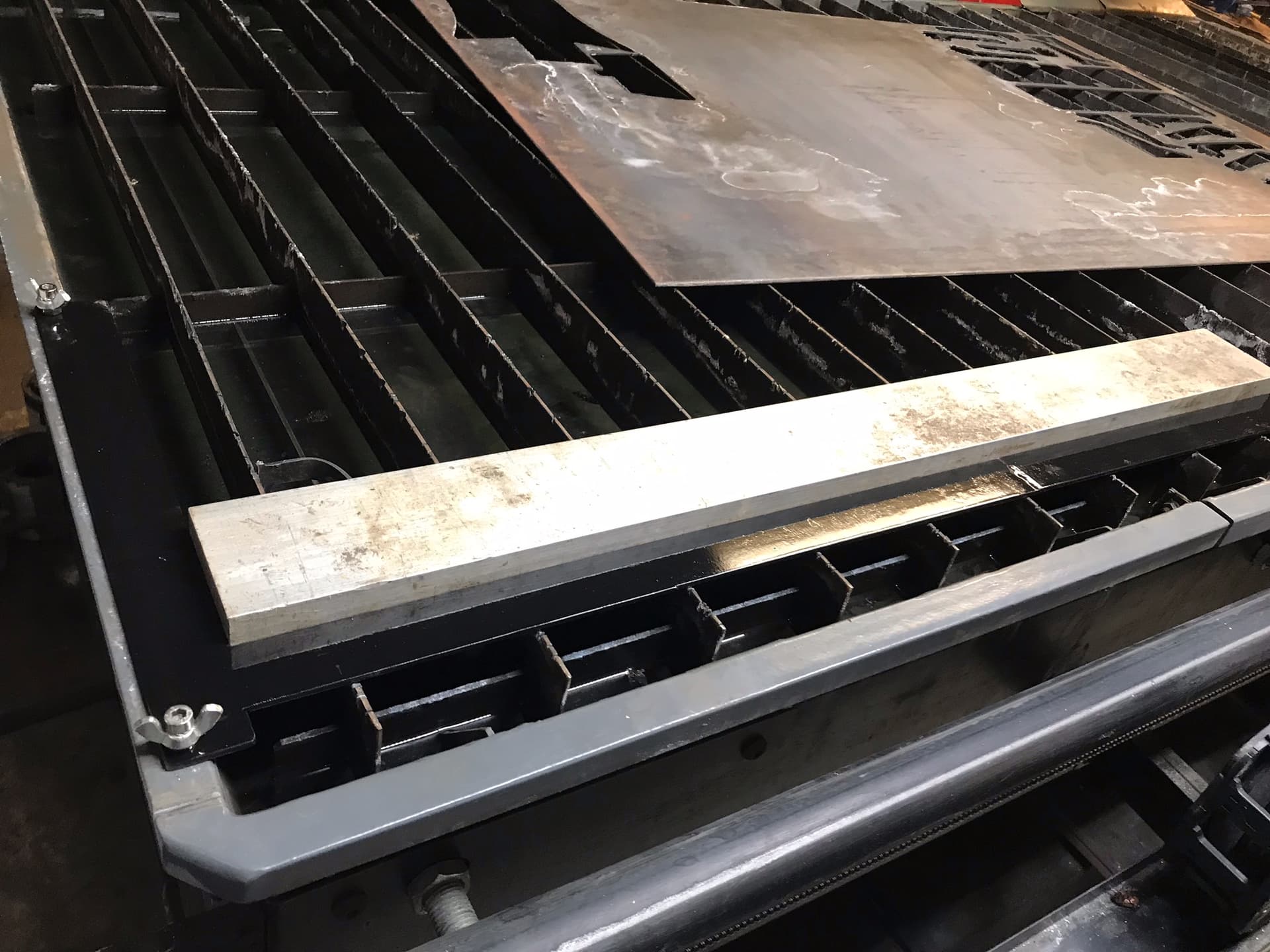
I bolted this 1 x 1 square steel tube to the table brackets. It allows me to quickly place metal either direction in a square or perpendicular fashion. I use a carpenter square against it for placement of metal along the x-axis. The torch kerf is still about an inch away from it at the extreme left position.
Yes so far the splash guard design looks good they looked like shit after hat 4x8 sheet was burnt but the floor was dry. A simple wash down with a spray bottle and paper towel cleaned them up except for the burn through my son did changing the soft limit to 48.5 in X axis to sever the 48.5" x10 ft x 1/4" sheet. We can pull it and weld it up but not a big issue. We typically just burn the 48" sever and use a cut off wheel for the edges. I can post a video of the splash and spark show at edges on the next sheet that gets burned, 4x8 10 ga. Ken
I tested some concepts and so far looks like I may have a plan. Main issues is Fire control homes then X + is cool but Y wants any moves to be -Y . I can deal with it but annoying. Sheet can seems similar. I see several maybe other plasma cutting machines true .000 is in lower left but the LM XR machines homes 96" from that, maybe a way to not infringe on a lawsuit and make us work a little harder?
Basically with most digital machining centers when you home and move all SB + .000 in unless its inverted in software or . Ideal concept in my mind was to set this stop concept so it works somewhat like a mill. throw flat bar in datum corner and go cut holes profile etc no perimeter cuts using existing stock edges.
These are all concepts at this point so take it and see if anything makes sense. Understood it takes some layer controls to drop the bar in with no profile but basically program all G code as interior cuts or hole pierces for precision drilling. Ken
I had to do something similar with layer controls a while back. I had to cut a design into an old saw blade but I needed the outer profile to center everything with. Ended up doing the origin as the arbor hole then just paused and ended the cut when it got to the final outer path. If I had to set up a jig for tubing, I’d be tempted to just have the outer profile be the first cut, then when I opened it in firecontrol I’d click on whatever hole was going to cut first and tell it to run from loop.
I can’t remember if you use Fusion 360 or SheetCAM for gcode but I was just wondering, with separate tool paths, before processing the gcode, could you delete the tool path with the outer contour?
Would it run correctly in that scenario?
I have done a similar thing that you do when I am cutting on a flat bar and want the entire width to remain. I have it at the end of the program: The first line of the outer contour severs the part from the rest of the bar and then I stop the program.
I suppose it depends on where you want your program origin to be for indexing. As long as you have a way to space the origin properly from where the cuts are in the tubing it will work.
So if you only had the holes in your code, you would have to have an origin over the tubing vs one off of the tubing if you included an outer profile? Im dizzy now
My thoughts are In sheet cam bring the dfx in with interior and exterior profiles, exterior being the outside of a flat bar etc that won’t get cut so a standard export. Then put all the interior cuts or any features on a cut layer maybe two if you were putting holes on one layer and maybe a one -2 sided exterior profile cut if that part needs that . Move the corner of the .dfx into the desired datum corner get all the tool parameters set. Then disable that layer. and generate the G-code .tap file. When it gets imported it will drop into fire-cam in the same datum but no cuts on the disabled layer ( not in the G code) pretty sure it will not generate a new origin. I payed with this with Sheet Cam and Fire Control quickly and seems it will work.
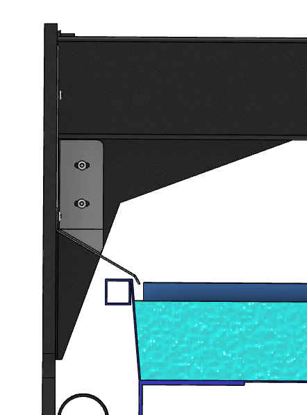
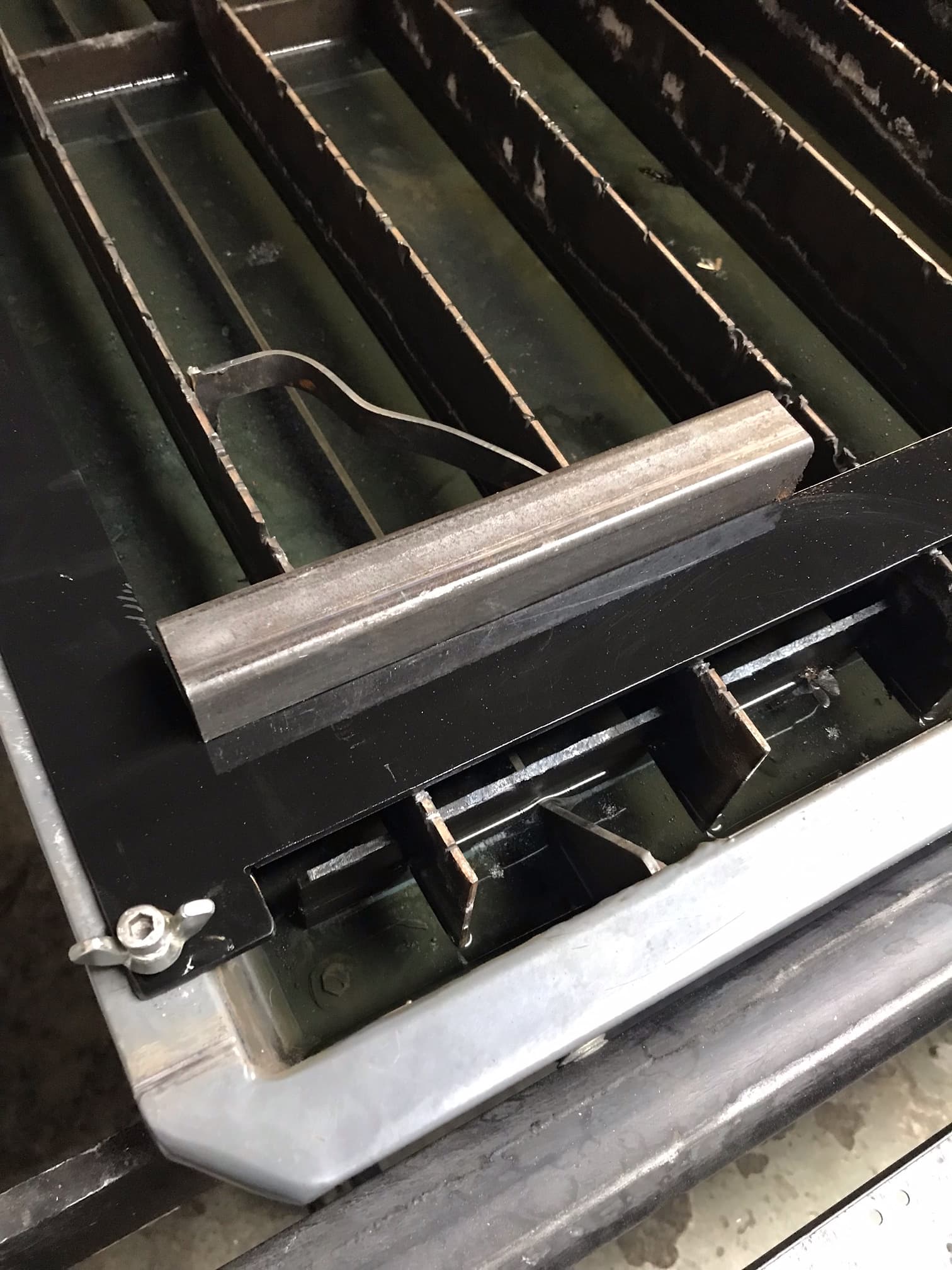
Thoughts are planning on welding some 2x3/16 flat bars making a 3 ftx 3 ft square corner and having appropriate extensions to allow it to be pinned to the X axis water tray on the home side. In the Y side of the leg another support will be welded to lower side but just a stop that is adjustable with screw and jam nut so it contacts the inside lower area of the water tray . A small set screw clamp can help lock it to one of the cutting support ribs. They are pretty stable and the X water tray dowels are doing most of the locating. The clamp is just to ensure if running a bunch of the same stock it is not accidentally bumped or deflected since the stop for Y is under water and may not be easy to ensure its against the inside of tray. extra clamp may not be necessary . This datum arrangement will be aligned approximately 3-3/16 off the home positions before its drilled pinned and adjusted.
Generate a rectangular cut .dxt with its datum at 3_ off each on=me position and let the machine cut that. using an inside offset cut so basically the cut should be at 3x3: off datum , it should be dead nuts square to machine travel and the cut corner dialed in to X3 Y-3. When in cad make sure the part being used for export has its datum aligned off the origins -3x-3y to corner of plate ( same as done for the jig cutting), Confirmed this works exporting from Auto desk inventor. so Fusion SB the same.
Home the XR machine, then in jog mode use 1" jog shift +X3" ( 3 jogs) same with -Y 3" . That sets the machine at 3x3 then zero work start point . The machine starts fro 0-0 ( actually 3x3) .
drop your tap file in (. dxf created with origin 3" off XY cad origin) it will drop it right on the datum the machine is set at. Cut and remove flat bar , replace with another flat bar repeat cut etc. Phase 2 may be add additional drop in spacers to stage a row of bars or tubes at even offsets and profiles can be cut on a few aligned patterned parts before stopping. Not sure that tube example image shown can do that as I don’t see 2 datum exes to align those tubes.
Hope some can follow those thoughts I stated doing a little modeling on this since I have some parts of the machine started in cad. This will take a little work but may be pretty cool to quickly drop bar stock or square rectangular tubes in to profiles off corner of stock XY as a cut datum to make a few or more parts, Smilar to a milling operation but no vice or milling cutters.
As far as severing the bar stock we can stack and cut a stack of parts to length on the saw so really was thinking this would be inside cuts, potentially interior holes and or slots etc and a profile the long dimension .
Ken
If you are going to cut thru the entire width of the flat bar, place a piece of scrap up against the flat bar where the cut will be started. This affords the torch something to sense, otherwise it might grab hold of the edge of the bar when it tries plunging and there is no metal to stop the plunge.
Jim initial thoughts are interior geometry. I only added cutting a profile on one side as a 2nd thought but as you mentioned I would dial that profile to maintain the arc and if cutting real close to an ext edge not on datum to maintain outermost edge yes drop some scrap near it. Probably lost a lot of folks with this discussion and should have just done it and showed the work. Interesting small test to see where folks are on a topic like this. I have been designing and building automation and manufacturing equip >30 years. This is my son’s machine just helping him a bit. Maybe, I can delete my start thread and all of this and start with how to do it. Be safe out there. K
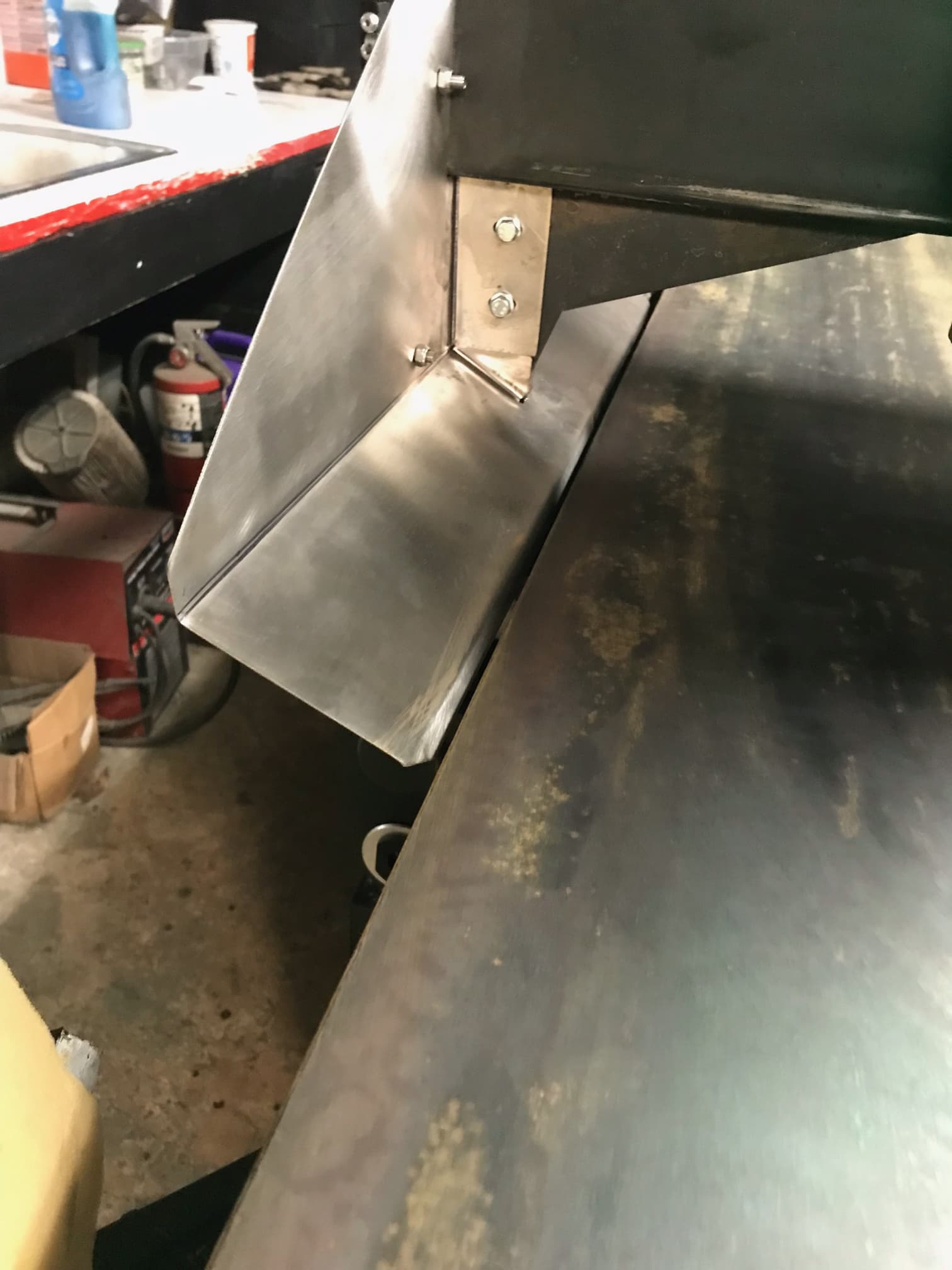
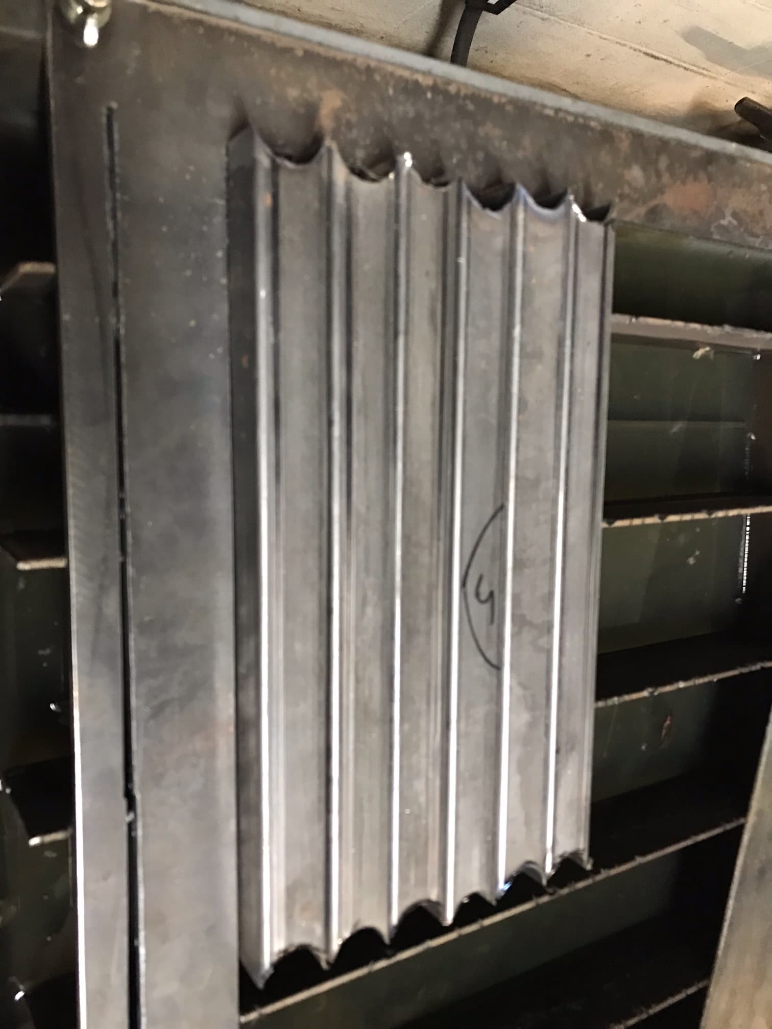
Back at this today . Some good results some learning on it as well. I see a lot of potential in this.We are more challenged since we are running our splash shields that don’t allow attaching to the Y axis water pan tubing. Had some issues cutting the long Y blade as the stock started warping . Pulled it back in and added a tab with a vertical blade that locks into the water tray rib so that long Y guide stays true. I have some thoughts if I do this again .
In the above 2 images you see the 2nd Y cut manually done in fire control,. away from the datum that was to try and warp the blade back it helped , really wanted it 2" but its good .
Corner Datum is 2" X 0" Y axis so for running holes and features in tubes or flat stock. No perimeter cuts only inside cuts with cad data with datum’s adjusted to Zero X and Y and move part 2" in sheetcam unless the part export plays fair and drops you in at 2" X and Zero Y. The m6 threads were tap drilled on the mill then aligned to ensure the machine would cut a margin out then the Jig clamped in place and tap drilled M6 followed by matched in place tapping so no slop in any holes although we still pull it on the long Y beam even 0 slop is some slop at 44" it seems. Now that the end of the Y guide is locked its solid . Should have that lock tab in 1st then cut the 90 live and learn in this life.
Finding I need to leave a fake perimeter cut in the G code so when dropping the tap file into Fire control it knows my perimeter datum corner. So far I have programmed an operation in sheet cam at the end and just pause and kill it before it tries to cut perimeter . I am investigating modifying sheet cam operation on perimeter or manually deleting start torch on perimeter cuts . Like not to have to run note pad as a 3rd operation to eliminate torch starts on perimeter And have another thread started relating to just truncating the G code after all the main cuts are done and before it even wants to run to exterior. All thoughts are welcome I will share a video or two on this, so far seeing good results running smaller drops or bar stock even modified a 4x4x1/4" steel angle leg ripping it from 4" to 2.688 and adding holes x2 pcs for our bending die.
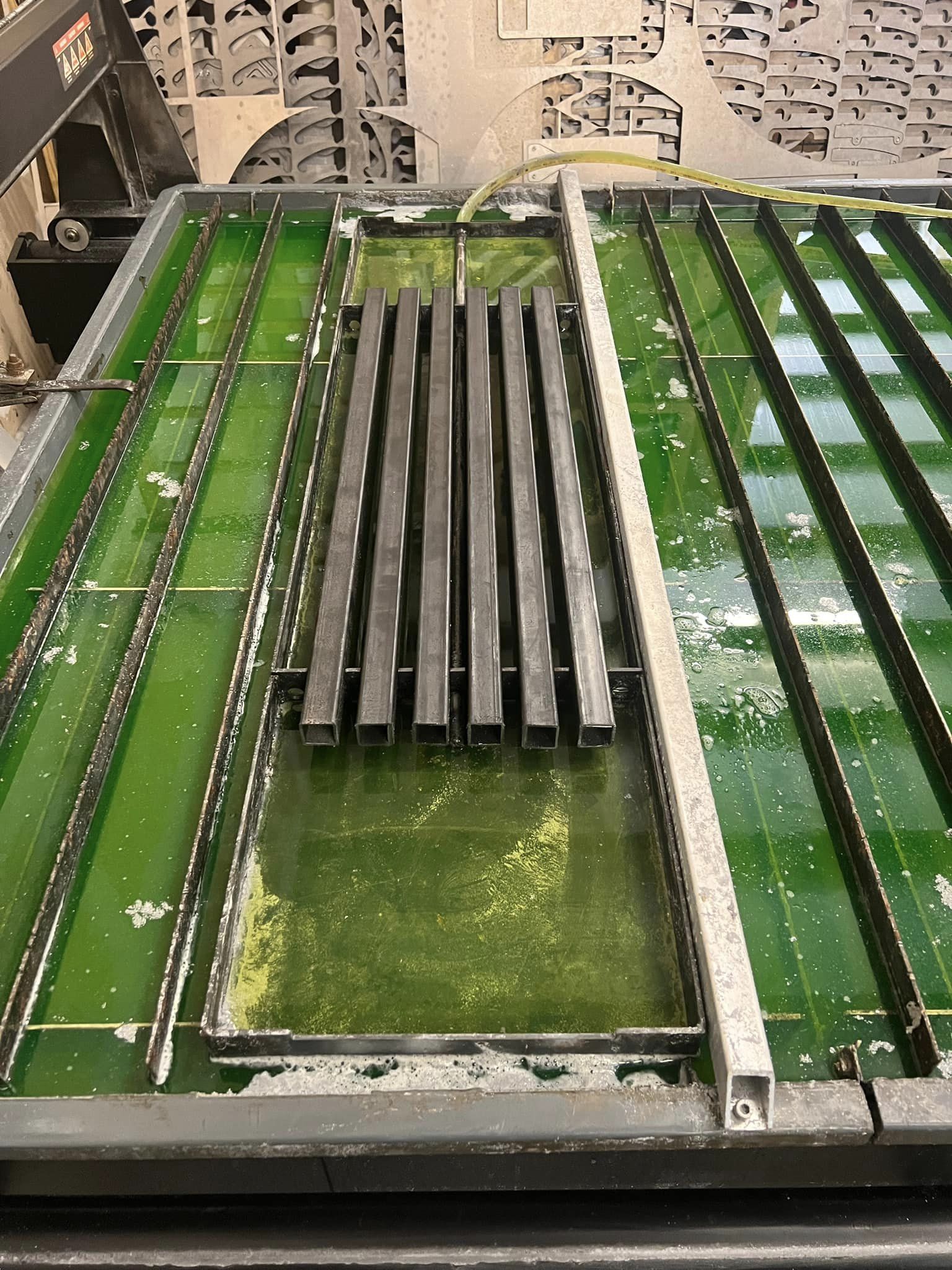
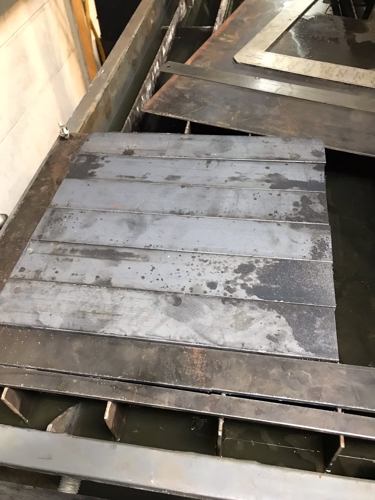
Some progress here:
We let sheet cam run a perimeter operation with no lead in on perimeter as a last operation . Then let Sheet cam generate the G code followed by open the tap file in notepad and , scrolling to the of the program end leaving the last two lines ending the program and scrolling up to the last rapid advance pointing to cutting the perimeter. The start of the perimeter start point should be at the closest x and furthest -Z position . Basically the original start point is preserved and the rapid to perimeter cut is intact but no lines to cut. We were cutting some small drops we saved to make some simple spacers and can see localized cutting common in a datum corner takes a tole on slats , We may remove all the slats if doing small work like this in the work space. We found some saw cut 1.5x1/8 angles standing on end can be positioned as needed and used at a slat . in small parts in multiple runs the small support angles get somewhat attached to the parts cut so those as of now are coming out after every cut and a paint brush sweeps debris off the water tray floor and the angles cleaned up and re positioned. that is a small pain . some small custom stock supports may be ideal positioned at no cut areas but suitable for touch offs or Alt end up with a batch of angles and after each cut just replace sweep the tray and cut.
Mind ticking make some tripod/quad support points out of drops and no dross touching them so simple lift out . Keep in mind this is related to cutting 4 parts out of a 2.4 square 3/8 drop off the machine. this Forum seems pretty dead in some regards I may stop . there is a XR FB page I am on but just the same stop sharing ? K