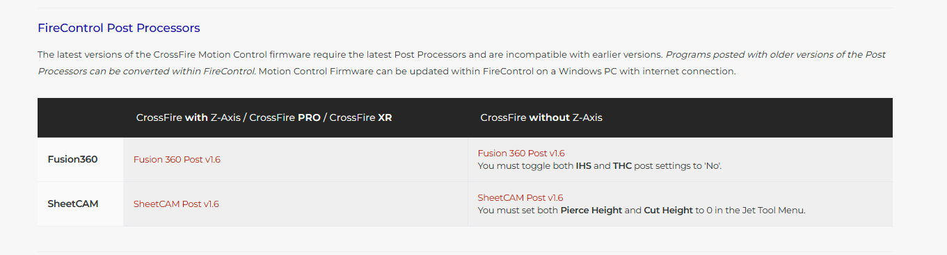
First, before even following these steps, you need to have a “tool” in your Fusion library for the metal thickness you are going to cut. You will also need to have the “Post Processing” file setup for FireControl. Look on Langmuir website or YouTube.
Go thru this entire tutorial:
https://www.langmuirsystems.com/software/fusion
Download for Post Processor:
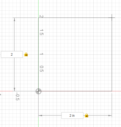
Now making the 2x2 image is simply picking the rectangle tool, form a rectangle, use the tab keys to enter “2” in the dimension of one side, tab to the other dimension and repeat. Now press [Enter] and you have your square.
Now move to “Manufacturing”

In Manufacturing, you need to create a “SetUp”

This is the menu that will open:
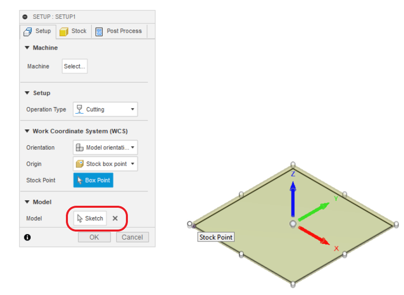
To simplify, you can do the bare minimum and simply click “OK” if you see that there is something appearing in “Model”. In this case, it is showing “Sketch” in the Model so that will work for us. I will move the Stock point by clicking on the left lower corner point.

Click OK. Now move to setting up a toolpath, by clicking on “CUTTING”, if prompted, you are looking for “Create 2D Profile” but it should do it by default:
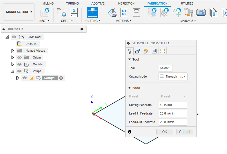
Here is where you need your “tool”. Since you are using 1/8" metal, you need a tool that has the kerf width and the cut speed relative to your cutter. Those are basically the only two values that you might have flowing thru to the post processing screen so those will be the most important values that you enter in the “tool.” I picked my 16 gauge tool in this example.
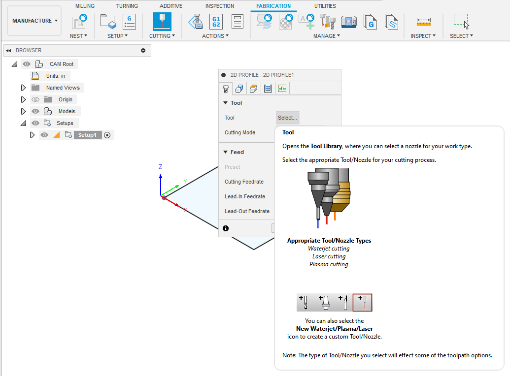
When you click on the tool in that first tab, this screen will open:
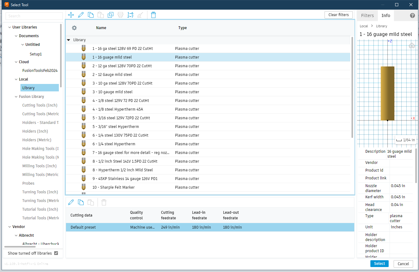
Select your tool and click on “Select”. Now you move to the second tab to select the contour(s). In this case, I am just going to use the “sketch” so I will click drop-down triangle to reveal the option of “Sketch Profile”
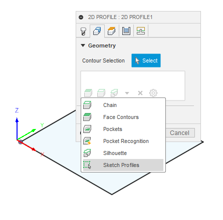
This secondary menu will open. Don’t worry to mess with anything in that window. Just go to the browser tree on the left of the screen and open/reveal where the sketch lives. Sincle click on the sketch and Fusion will grab it.
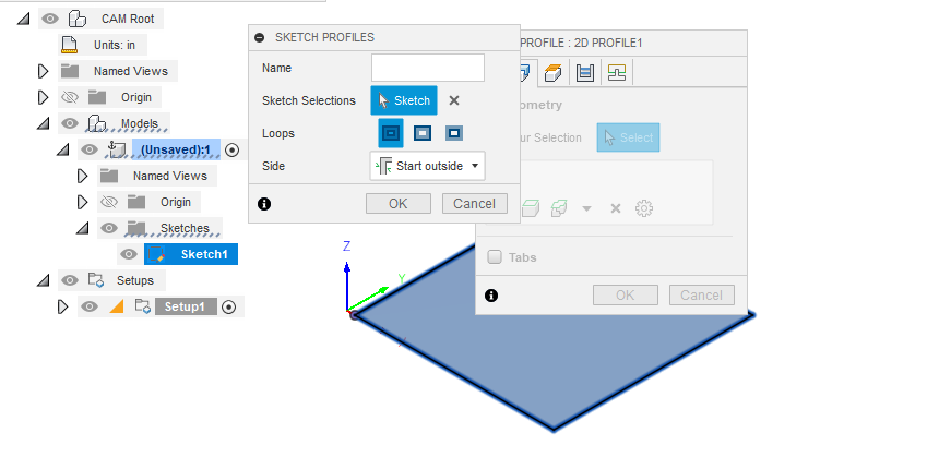
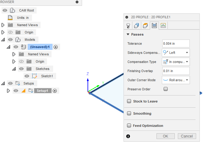
Click “OK” on that Sketch Profiles menu. Now move to the fourth tab of the 2D Profile. For simplicity, just pick what is shown in the example. What is most important is the “Sideways Compensation”…it should be set as “Left”. That means that the direction the torch is moving, it will be to the left of your finished piece.
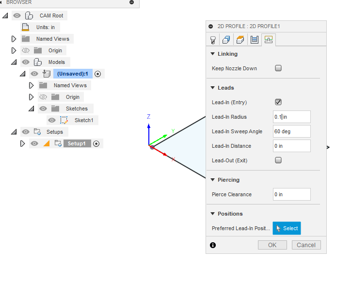
Now move to the fifth tab. Again, for simplicity some sample settings are given. A good rule of thumb is the ALWAYS set your Pierce Clearance to “0”.
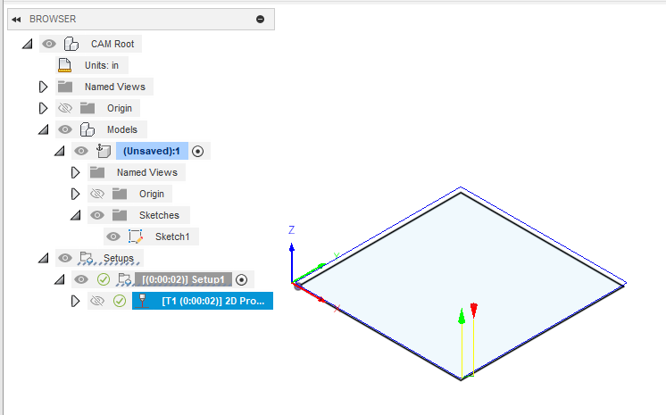
If all worked right and all contours had a valid cut path designed, then you will get green checkmarks next to the toolpath(s).
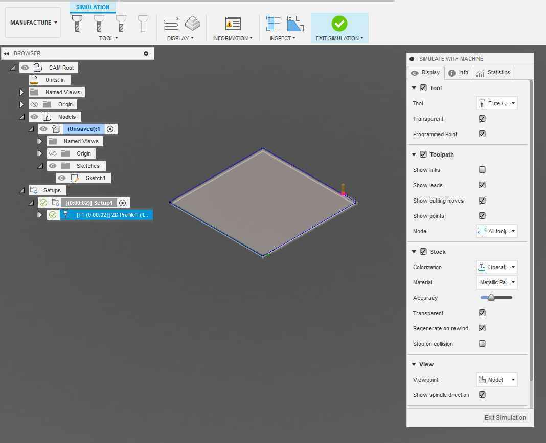
If you want, you can run the simulation, but it is not necessary:
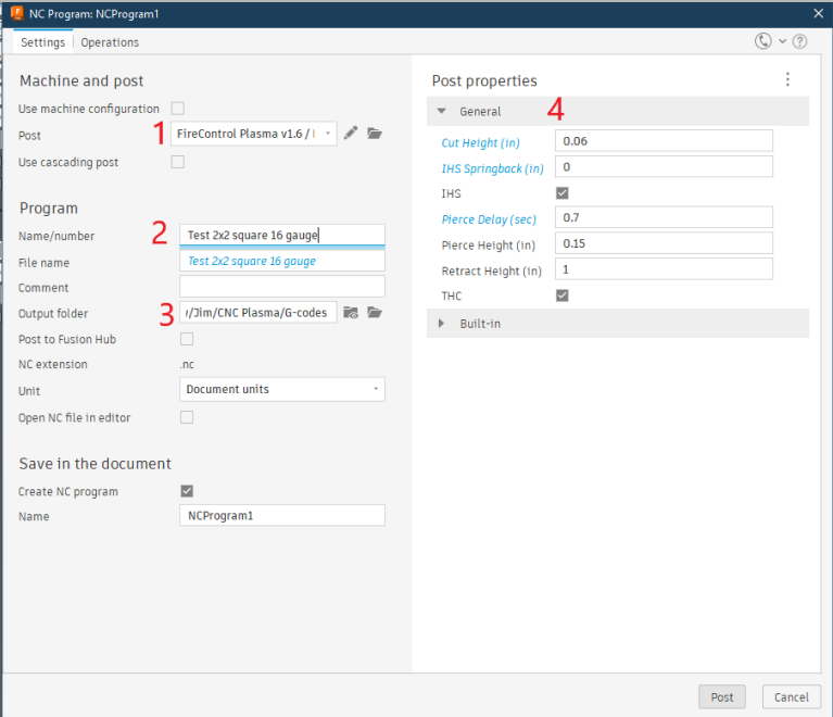
Now move to creating the gcode (Post Processing):
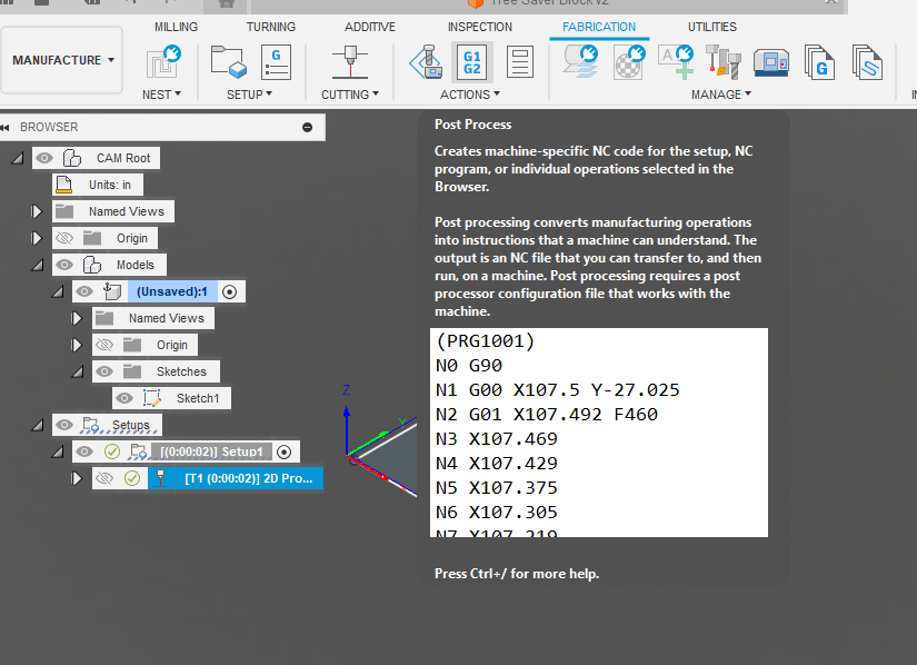
In the post processing screen you will see that there needs to be the post processing file set up (1), you give the file a name (2) and tell the computer where to save it (3) and the actual cut values (height, pierce height, springback, pierce delay) (4). If you have an active Z axis then you will put a check mark for “IHS”. If you have Torch Height Control, you will put a check for “THC.”
You will then open FireControl and load this gcode file which will have this name format: xxx.nc if it came from Fusion. If it came from SheetCAM it will be xxx.tap. Either will work.
Once you cut your square, you measure the dimensions. If you are at 2.05 inches then you would reduce you kerf width by 0.025 inches which moves the torch closer to the line. If your actual cut was 1.94 inches, you would increase your kerf width by 0.03 inches which moves the torch away from the line by that amount which in this case was 1/2 of the deviation.