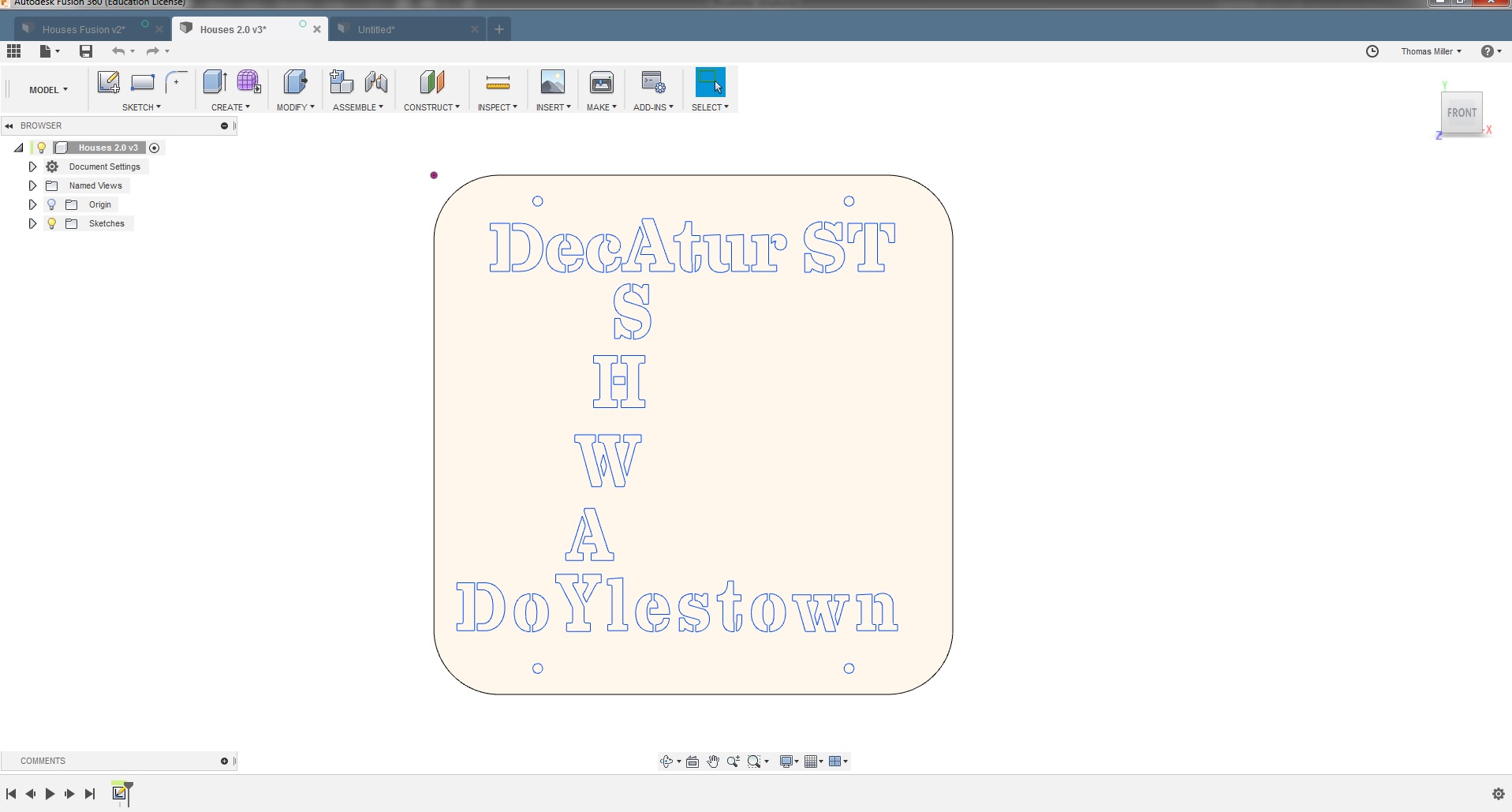
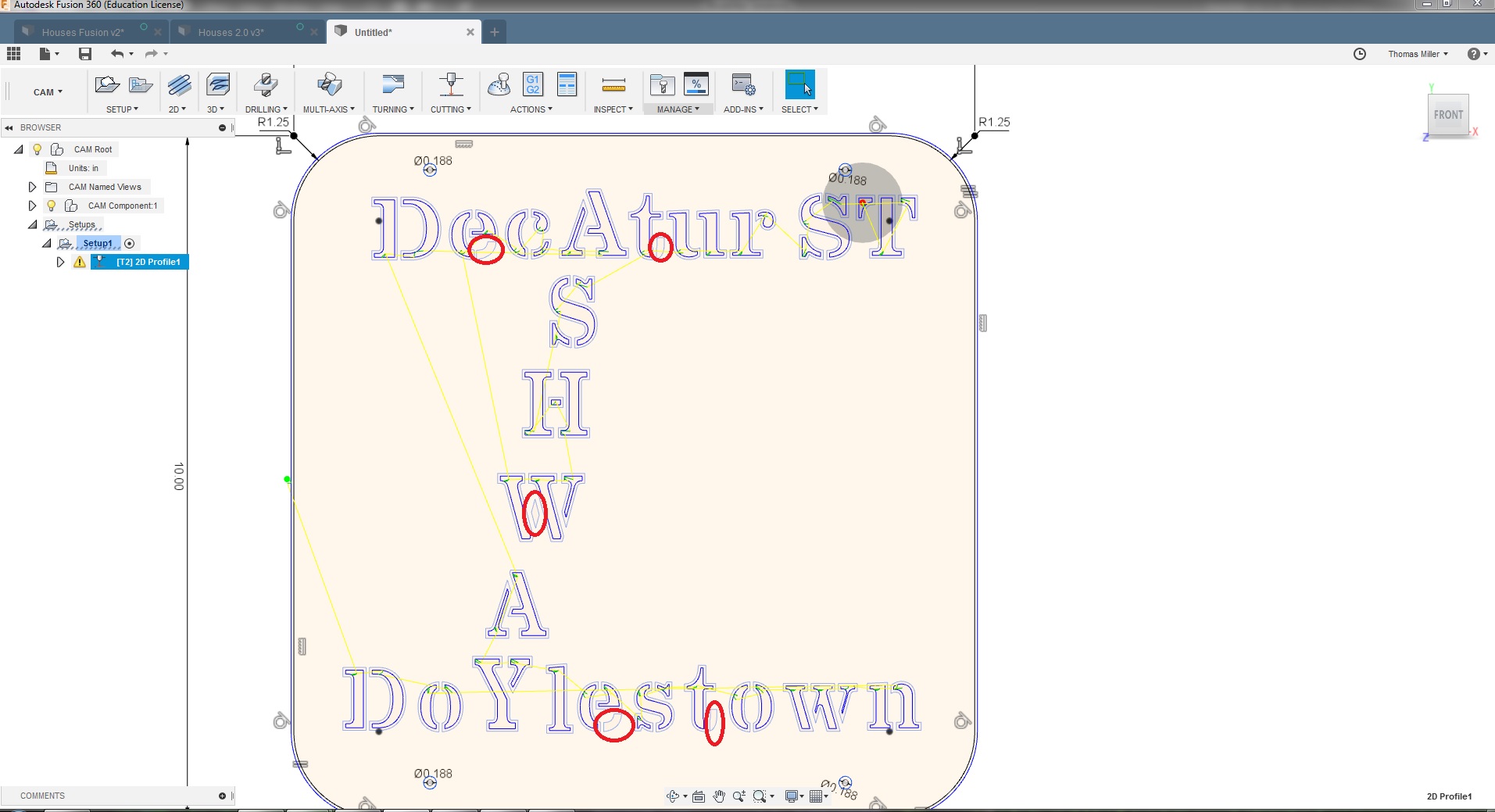
So I’m still pretty new to Fusion 360 so I’m not sure what I’m fully doing. I’ve got this project I’m working on for a neighbor. Pretty simple sign with some text on it. Once I got my machine together I cut out a test, for the most part, it came out “ok” but I wanted to change some things around… So now I’m back in cam trying to finalize the sign. Also worth mentioning I designed it in adobe isolator and have tried exporting in both.DFX and.SVG both with the same result. I set up my stock and moved on to my tool path selected all my geometry then went back and checked all my arrows 95% is fine and ready to go but there are a few geometry pieces that Ijust can’t get to become tool paths
This happens in Fusion when the line segments don’t touch. Zoom in very tightly and try using the extend tool to get the segments touching and it should resolve it’s self. I’ve had this same thing happen from time to time when working with SVG’s (I don’t work much with imported DXF so I can’t say if it’s more common with one type of file or the other).
Bruce
2 Likes
Ok, I took a look at your drawing. It’s not a line connection issue. Your Lead in distance on the 2DProfile is too high. Under the Linking tab look for lead in distance change that to be a little lower. You’ll have to test it and see how low is too low but I’m guessing that 1.5X the kref Dia to 1.25x the kref is about it… If you have scrap test stock run it at the kerf dia see how it does. The other thing I noticed is you were starting from the outside. If you want to make a sign not cut out letters you may want to have it start on the inside. This way any pierce and lead in is in the waste material.
Bruce
3 Likes
I would agree, this looks like more of an issue with the lead in size.
@rccrazy30, you may decide to break this part into two cutting operations. The first one would be to cut out the fine details where larger lead-ins wont fit. The second operation would be used to cut out the larger cutouts and the perimeter.
1 Like
That was it! I was initially thinking the same thing since the warning mention a linking constraints. I created 3 operation’s #1 I have it cutting out the smaller parts with a .01 lead in #2 cuts out the larger letter’s and #3 takes care of the sign. I also changed all the letter operations to start inside.
I sadly don’t have any scraps yet to practice on yet. Hopefully next week I can make my way to a metal supply to pick some up.
Thanks for all the help ill Post a photo once I run it.
3 Likes
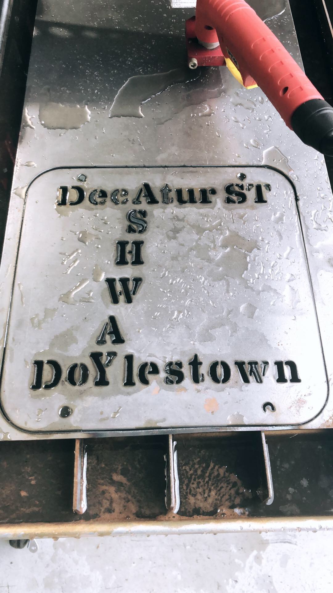
This went much better then my first attempt. Still had 2 minor issues
#1 I started the program at the lower right hole and It didn’t fully cut the hole all the other holes cut fine.
#2 was completely an oversight in cam I missed one of the sections of the letter oops lol
3 Likes
Looking much improved!
Ive noticed that some plasma cutters take sligntly longer to fire on the first pierce. You may consider increasing the pierce delay just for the first pierce.
How do you program a different time for the first pierce rather than all of the pierces? If I recall, the video tutorial showed setting the pierce time once when you post the g-code?
1 Like
Hey what font are you using?