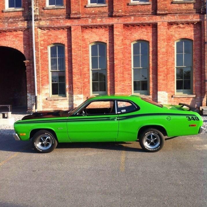
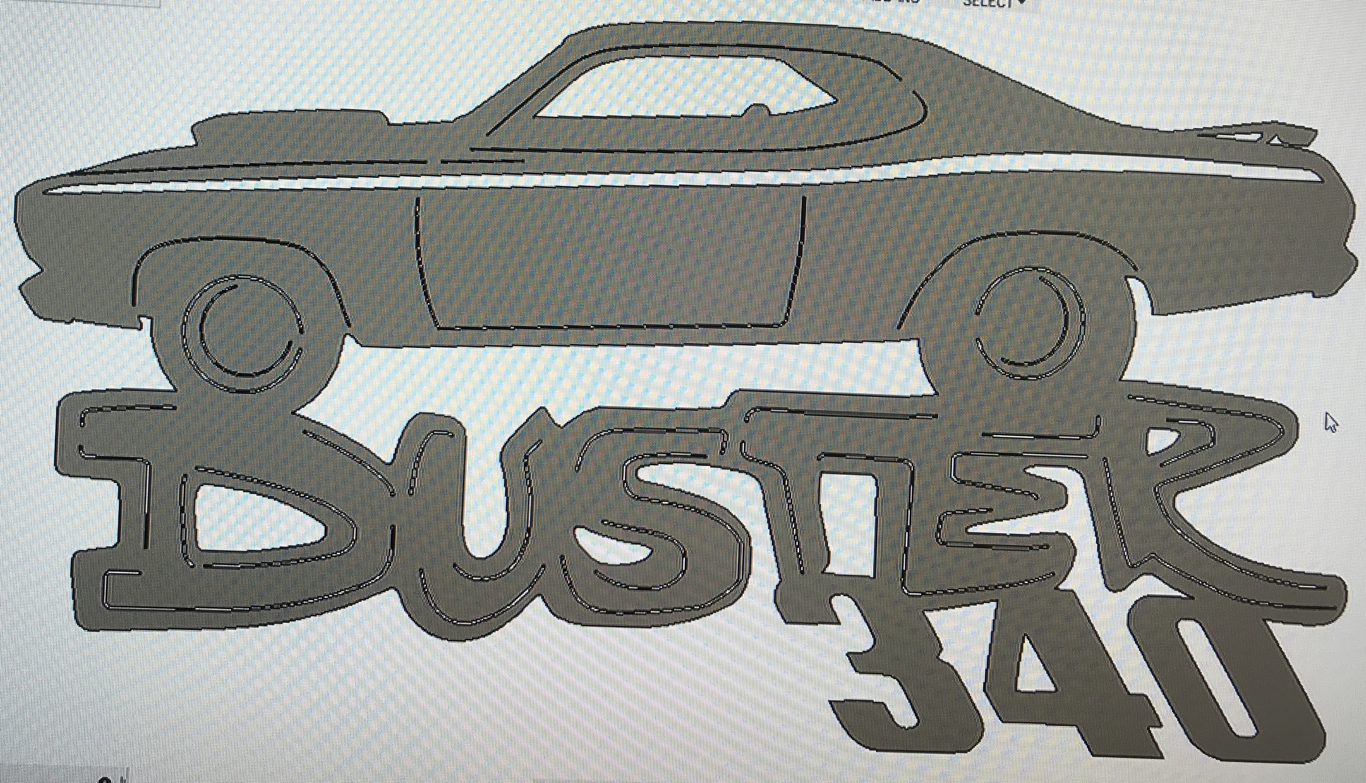
Got commissioned to make a Plymouth duster sign by a woman for her dads birthday. Bit of work but I’m ready to cut. Had to make it in 2 separate cut files so I could cut the inside lines as a single pass. Going to be 2 colours. I bought a dxf of the duster and added the wing and 340 to the bottom, had to remove one side of all the inside lines to have it cut.

2 Likes
Nice. That was a sweet car (I’m and old fart who remembers those when they were new  )
)
Why did you have to make 2 cut files? Or did you mean 2 separate toolpaths? I’d think 2 cut files would make it more complex to make the project
I set the tool path for the single line cuts on the inside without the image extruded. Figured it would be easier to use the same setup in manufacture but extrude the image and have it cut everything else as a second .tap file.
I’m just winging it because I haven’t tried anything like this before.
I guess I could select all my toolpaths on the non extruded image and have it all as a single .tap file, but I’ve had stuff cut on the wrong side of lines before trying that because it wasn’t clear which side the arrows were on the line selection in manufacture.
Ah. You can do that in separate toolpaths but keep them in the same tap file.
BTW, I don’t usually extrude the files. You don’t need to though I know some people find it easier somehow.
I do zoom in, often a lot, to see where it’s going to cut. I’ll run a simulation as well. I look for where the drawn line vs cutline show up. I also look to see where the lead-in shows up. All of those tell me whether or not it’s going to cut on the right side of the line.
One tap file (usually) makes it easier to run the project in Mach 3 without worrying about misalignments because the material shifts or something.
1 Like
I will redo my .tap file into a single one because I think it will be easier like you said for this project.
I like to extrude an image normally because I can click once on the body and it will do all of the tool paths and they will be on the proper sides of the line to cut, without it extruded I need to click each path and make sure it’s on the proper side of the line by zooming in. However I’ve had the arrow not show which side it’s on even zoomed completely in before.
That’s why I look to things like the lead-in arrow ![]()
1 Like
Good tip!
Now that you mention the lead ins that’s also the reason I did 2 separate .tap files. I had to set the inside image single cut lines as no lead in or out and no pierce clearance, didn’t want the rest of the cuts like that or it would make a mess. Or can I still just make a second tool path with different lead in/out settings under the same setup?
Yes. Exactly. ![]()
The only setting you can’t make different is the pierce delay.
1 Like
Ok great. Just went ahead and redid the whole thing as a single .tap file.
Thanks for the help James!
I always extrude because when it’s extruded fusion knows on its own what side of the line to cut on.
1 Like
Tried to pick the outside contour without it extruded and it was only selecting short segments at a time. Would have taken me half an hour to click around the whole thing. Extruded it and selected the outside as a single cut on a separate tap file. Cut great
Got it. I expect it’s because your files are coming over as splined DXF. I do my design work in Corel for the most part (occasionally Inkscape) so instead of a bunch of segments I have continuous lines. If you’ve made sure you don’t have disconnected segments (there are add-ins for Fusion that can fix that - I’ve posted on one or two if them), then you might want to try using SVG files instead of DXF.
I don’t extrude because I want control over which side & what order I do cuts. I usually have 4 toolpaths at least that I define - one is for line cuts where it’s not a shape, just a line and I want to cut those without an offset, lead-in or pierce delay. A second one is for small holes where I know I can’t fit either an offset or lead-in. The third one is for all internal offset holes that are big enough to support a lead-in. The last is for all outer offset cuts. So I do some amount of clicking but it’s by object, not multiples for every object in the design.
Check to see as well if your DXF files are splined & can be saved with the ROBO format instead to get rid of the segments. I have a post on Polyspline vs ROBO formatting for DXF files that might help explain things a bit more.
1 Like
I have used Coreldraw for many years but haven’t figured out how to get the drawings into Mach 3.
How are you doing it?
I draw in Corel, save as either SVG or DXF and then insert the SVG into Fusion for toolpathing or the DXF into Sheetcam for toolpath definition and generation of the G-Code for Mach 3.
I only draw in Fusion when I’m making a 3D part or if I’m going to use some of the features for manufacturing that allow me to define the “output” size and let it calculate the adjustments needed when the material is going to be bent or folded.
Both Fusion & Sheetcam can toolpath either SVG or DXF files but I’ve found I get better results (e.g. program doesn’t freeze or crash or take forever to render) if I use SVGs in Fusion and DXFs in Sheetcam. Other people don’t report similar issues so it may be something unique to my setup but it works so I haven’t spent a lot of time trying to figure out why 
I can use my Corel designs for either laser or Crossfire (even for the Shopbot). One laser wants SVG and the other only uses DXF so I’m used to saving in the format the target machine needs.
Thank you for the reply. I was hoping to not need another software. I guess I go for Fusion for a hobbyist…
None of the 2D design applications like AI, Corel or Inkscape have the CAM part that you need to define toolpaths and generate the G-Code.
The 3D design packages like Fusion usually are CAD & CAM in one so you can do design and prep it for manufacturing. The problem is it’s a pretty steep learning curve and it can be really hard to make the transition from 2D design applications to 3D. And because they’re oriented towards making things 3D packages aren’t as easy for artistic kinds of work and don’t have some of the built-in tools to do things we do in Corel easily.