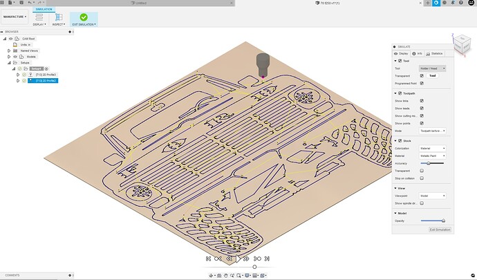
why does the tool path miss different points ?
I’m guessing this is Fusion. Some of the reasons are the space between lines is not enough for the torch to pass through in both directions without passing over an already cut area or the lead in/out is too large to fit inside the contour.
yes its fusion, i have set the lead in/out way down but it still wont pickup the larger cut area
Any chance you could post your f3d ,file we could look into it more deeply.
I’ve seen in several cases where people have their decimal places in the wrong place for some of these numbers.
Check your check your kerf width parameter.
I’ve seen a lot of .55 instead of .055
It is not what I was looking for.
Check out this link on how to create an export a f3d.
This file will give me all the information from that particular fusion design you’re working on.
It’s the right file extension so that’s a good start.
I’ll check it out when I get back to my computer
Weird that the f3d file you sent doesn’t include any manufacturing information you must have at least made a setup to have some of the geometry fail in the manufacturing setup?
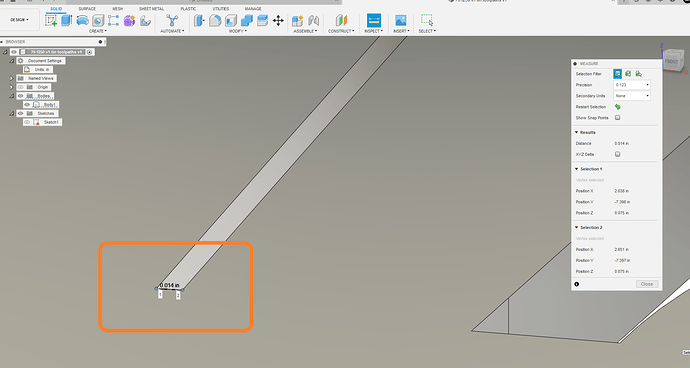
I can see one of the issues is the geometry that should be single line is actually a really really small slot about .014 wide.
Some of this missed geometry on the first tool path you should be able to pick up on the second.
I’m going to look at it a little bit more here
76 f250 v1 tin toolpaths v1.f3d (3.6 MB)
I did a 2nd tool path to pick up those micro slots as singles lines.
I believe this was the original sticking point that was giving you trouble.
see how this F3D looks, you should be able to look at the toolpaths how I did them.
I guy in town has an old ranger highboy in town, very cool trucks.
Tin Whisperer thanks so much, you make it look so easy. I really appreciate it.
I know right!!!..he is one great guy…

