Test cut program to find the ideal cutting speed

I’ve been meaning to write a simple program with variables and macros to run test cuts to find the ideal feed rate. But I have just been using feed rates that work up till this point.

It has been over a year since I have used variables, macros, or sub routines. And this was the first time I have tried any advanced programming in Mach3. Took me a little bit just to remember my M98/99 codes. Then took me a little bit to figure out how Mach3 wanted to see its Varibles, and Macros. And just when I thought I had everything figured out, I was still only getting 2 lines to cut. After some searching, someone said that the code file should start and end with a blank line, and the code must also end with a %

I ended up using 6 variables, but I labeled everything in brackets. You only need to alter 5 of those 6 variables to fit your needs. I mainly only adjust #100 (Base feed rate) and #105 (Number of test cuts). But feel free to change the others as you see fit.

Also the pierce dwell is in milliseconds, and the initial pierce is set to 1000 milliseconds, while the rest are set to 800 milliseconds. You can change this to seconds if you prefer, you may also need to increase or decrease the values depending on your machine, and material you are cutting.

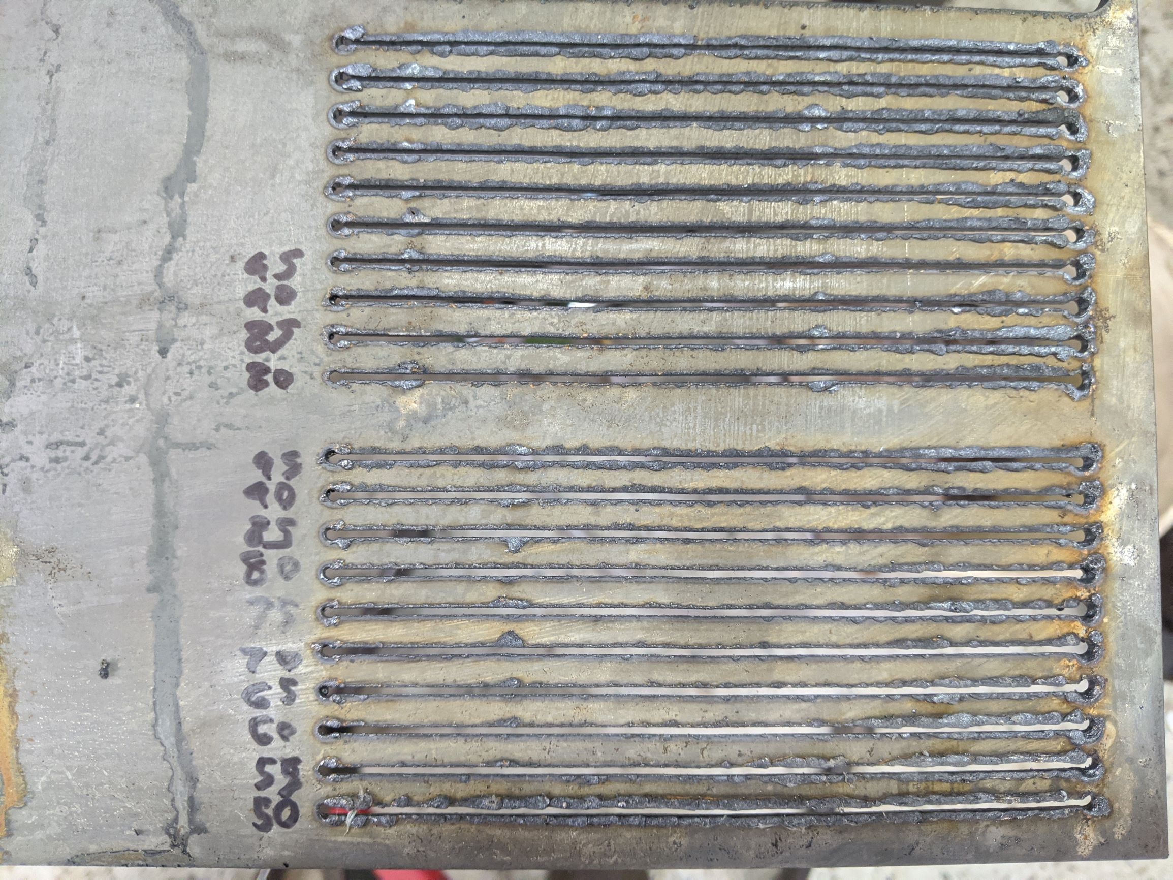
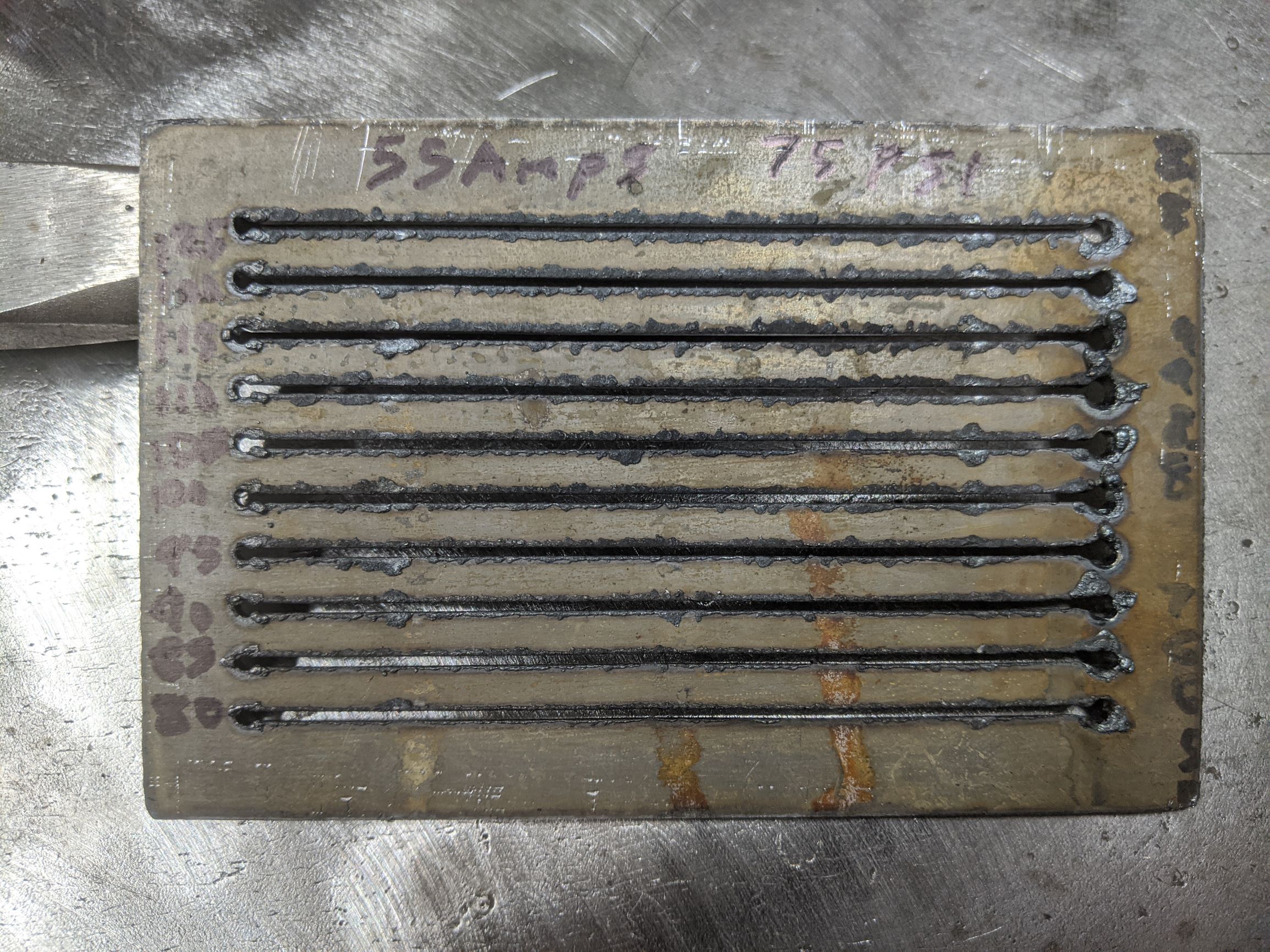
The way the code is set now, it will cut 10 lines starting at 80 ipm, increasing each cut my 5 ipm. The lines are 5 inches long, spaced .25 apart. The final cut will be 125 ipm.

I could write one that cuts out the test cuts when finished as well if anyone would like that.

Here is the program.

(Langmuir CrossFire)

(This file is for testing cutting feed rates using variables in the values below.)
(You may need to adjust the pierce values to match your cutting machine and material thickness.)

#100 = 80 (Starting Feed rate)
#101 = 5 (Feed Rate Increase per test cut)
#102 = 0 (Y Starting position)
#103 = .25 (Y axis incremental move per cut)
#104 = 5 (X axis length of test cut)
#105 = 10 (Number of test lines to cut)

G90
G70

(2D Profile1)
G0 X0 Y0
M3
G4 P1000 (Dwell in Milliseconds)
G1 X[#104] F[#100]
#100 = [#100 + #101] (Incremental Feedrate)
M5
#102 = [#102 + #103] (Incremental Y Move)
G90
G0 X0 Y[#102]
M98 P0001 L[#105-1]

M30 (End Of Program)

(Sub Program)
O0001
M3
G4 P600 (Dwell in Milliseconds)
G1 X[#104] F[#100]
#100 = [#100 + #101] (Incremental Feedrate)
M5
#102 = [#102 + #103] (Incremental Y Move)
G90
G0 X0 Y[#102]
M99
%

And here is the results of my test cuts in 11 gauge steel at 55 amps, cutting about .125 off the surface. I first started at 50, then ran another starting at 80, stopping at 120 as I was running out of space. 85 ipm looks to be the sweet spot for this setup.

8 Likes

Very nicely done. This is exactly what folks should do. It’s similar to the test matrices we do on lasers to find optimum settings for different materials. This is good to run for each nozzle size/material combination. I always use the max power for the tip so I don’t need to vary the test by power too.

Excellent, thank you for sharing!

Very useful! Thanks! As I’m about to start evaluating my new CrossFire and cutter, this couldn’t be more timely!

A couple of questions:

  1. It seems as if there was enough consistency within 3 inches that cutting 5 inches wasn’t necessary. Would you agree (now that you’ve gotten some learning on this)?
  2. What Cutter are you using and what air pressure & nozzle size were you using?

Thanks again!

3 inches might be enough, but I dont mind using a little more material on test cuts like this. Easy enough to change the variable as you see fit.

I am using a Everlast 60s machine, I think I was running around 70psi?

Very nice, I will be trying this out in the next few days.

Thank you for sharing.

I decided to tweak the code to include the cutout program. I also turned the start piece and main pierce into Variables so that they are easier to find. The cutout will use the starting feedrate. Again everything is commented, and all of the adjustable variables are up top.

(Langmuir CrossFire)
(This file is for testing cutting feed rates using variables in the values below)
(You may need to adjust the pierce values to match your cutting machine and material thickness)
#100 = 80 (Starting Feed rate)
#101 = 5 (Feed Rate Increase per test cut)
#102 = 0 (Y Starting position)
#103 = .25 (Y axis incremental move per cut)
#104 = 4 (X axis length of test cut)
#105 = 10 (Number of test lines to cut)
#106 = .5 (Outside cut offset)
#120 = 1000 (Start Pierece Delay in Milliseconds)
#121 = 600 (Main Pierce Delay in Milliseconds)

G90
G70

(2D Profile1)
#102 = [#106] (Y start of first test cut)
#104 = [#104 + #106] (X start of first test cut)
G0 X[#106] Y[#102]
M3
G4 P[#120] (Starting Pierce)
G1 X[#104] F[#100]
#100 = [#100 + #101] (Incremental Feedrate)
M5
#102 = [#102 + #103] (Incremental Y Move)
G0 X[#106] Y[#102]
M98 P0001 L[#105-1]

(Cutout)
#107 = [#104 + #106] (Length of cutout)
#108 = [[#103 * #105] + #103 + #106] (Height of cutout)
G0 X-0.1 Y[#108]
M3
G4 P[#121]
G1 X[#107] Y[#108] F[#100]
X[#107] Y0
X0 Y0
X0 Y[#108]
M5

M30 (End Of Program)

(Sub Program)
O0001
M3
G4 P[#121] (Dwell in Milliseconds)
G1 X[#104] F[#100]
#100 = [#100 + #101] (Incremental Feedrate)
M5
#102 = [#102 + #103] (Incremental Y Move)
G0 X[#106] Y[#102]
M99
%

6 Likes

This is awesome, thank you again for sharing. Can’t wait to try it.

I like this new version where the test is cutout and effectively saved for future reference. However, looking at the code, it seems as if the cutout would use the ending feedrate, not the starting feedrate. It’s a nit, for sure, but I’m trying to verify if I understand the code.

Also, to confirm, is the ‘start’ pierce delay longer than the ‘main’ pierce delay because this is what should be done normally, ie, the initial delay has to be longer until the tip ‘warms’ up or is there another reason?

Ohh you are right, it is cutting at the final feedrate. Could add another Variable for the cutout feedrate.

The longer start pierce delay is there because others have recommended doing so. But every machine torch is different.

Cool. No problem on the feedrate, as you say, another variable can address that.

Thanks for the code and taking the time to post and discuss it.

I’ve used this code as a basis for an evaluation of the new plasma cutter I’m using and posted the results here: Lotos LTP5500D CNC Cut Chart

This post includes a link to my github repository that has the source code (and photos of results) I used for each material.

Thanks again for the original work. You will see in the referenced code that I cite your original work. Good job, again, very useful.

1 Like

I apologize if this is an eye-roll question, but I am absolutely new to the CNC world… how do you load your script to Mach 3? Do I copy and paste the code to Notepad and save as a .??? file type or is there a way to load directly to Mach 3?

I would recommend starting with the tutorials that Langmuir has provided at https://www.langmuirsystems.com/tutorials

With this file, you will want to copy and paste it into a notepad file.Then when you save it, change the “save as type” to “All Files (*)”. And the file name should end with .tap

You will also want to either change the pierce delays to seconds, or go into mach3 and change the parameters to use milliseconds. Apparently there is a bug in Mach3 that can cause issues if the dwell is under 1 second, switching to milliseconds fixes this problem.

3 Likes

Thank you Mike_C… I appreciate your help.

Got a chance to try your cut program and I have to say that it works absolutely wonderful and much easier than what I had to do in the past for testing.

Thank you for sharing.

I just got a bunch of scrap bits of odd materials I do t use to test so this is timely thanks!

1 Like

Which is the peirce value?, Drawing a blank?..

Thank you Mike, this is a great help in finding the best cut speed with my Hypertherm max30. I found that it worked better for me (with this low amperage plasma cutter) to start with the highest travel speed and reduce it for each successive cut. I just made the 101 variable a minus value. This also helped with cutting out the sample on the heavier material. Having a variable for start pierce and later pierce helped determine a good delay time. I duplicated the file for each of the materials and thicknesses I am using and ended up with some really valuable test data. And I can reuse them any time I use a new material or thickness.

2 Likes

That’s what I did as well. Whenever I feel the need to tweak a particular material/thickness, I can just open the previous file, modify the parameters, and save it as a new version. The process is simple and allows you to adjust practically anything. For example, for 16ga SS, I found that I needed a much longer delay after cut to allow the blank to cool down before the next cut, my first go was almost a disaster as the workpiece warped well beyond usability.

1 Like