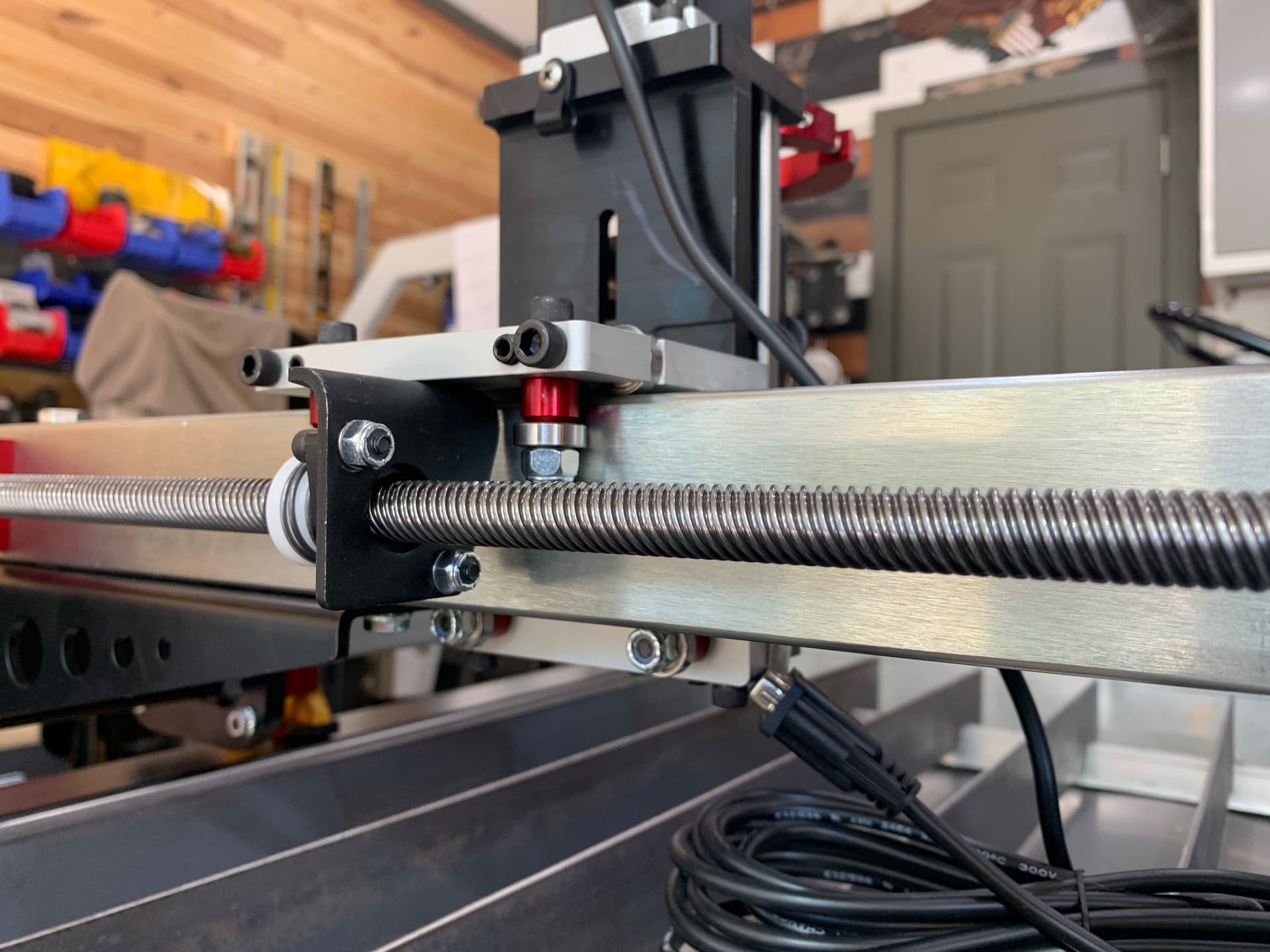
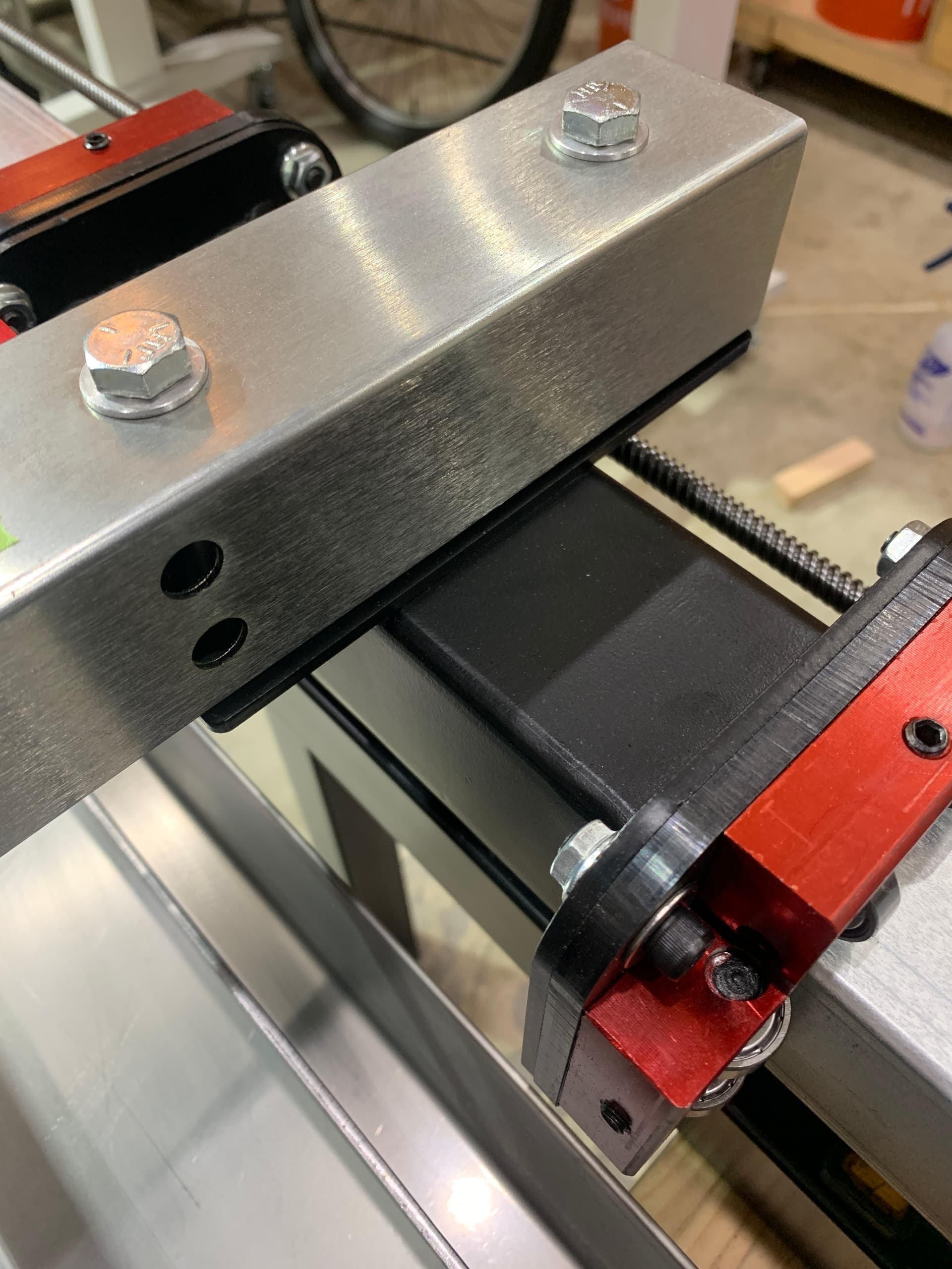
Just noticed a minor interference between the underside bearing retaining bolts and the long triangular support brackets for the X-axis beam…
The Nylok nut that holds that lower bearing in place sticks out maybe 1/16" too far and strikes the black triangular support bracket. If the nut were thinner, or if that small red anodized spacer behind the bearing was shorter, I suspect this would not be an issue. I can grind down the nut, or shorten the spacer… but before I do anything drastic I wanted to check-in with you guys. Most of this assmbly comes preassembled from Langmuir, and all I had to do was bolt on the actual torch mount plate.
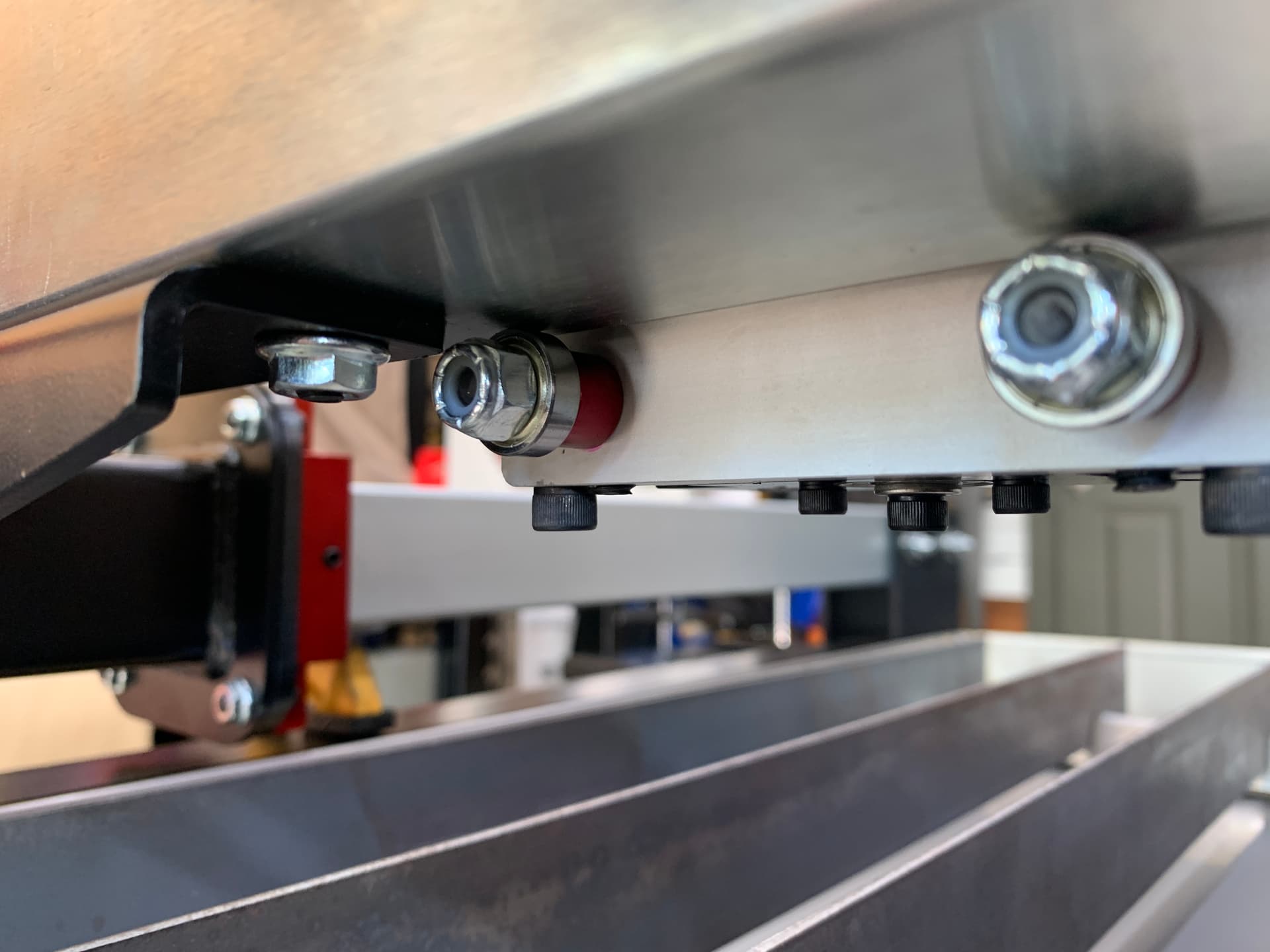
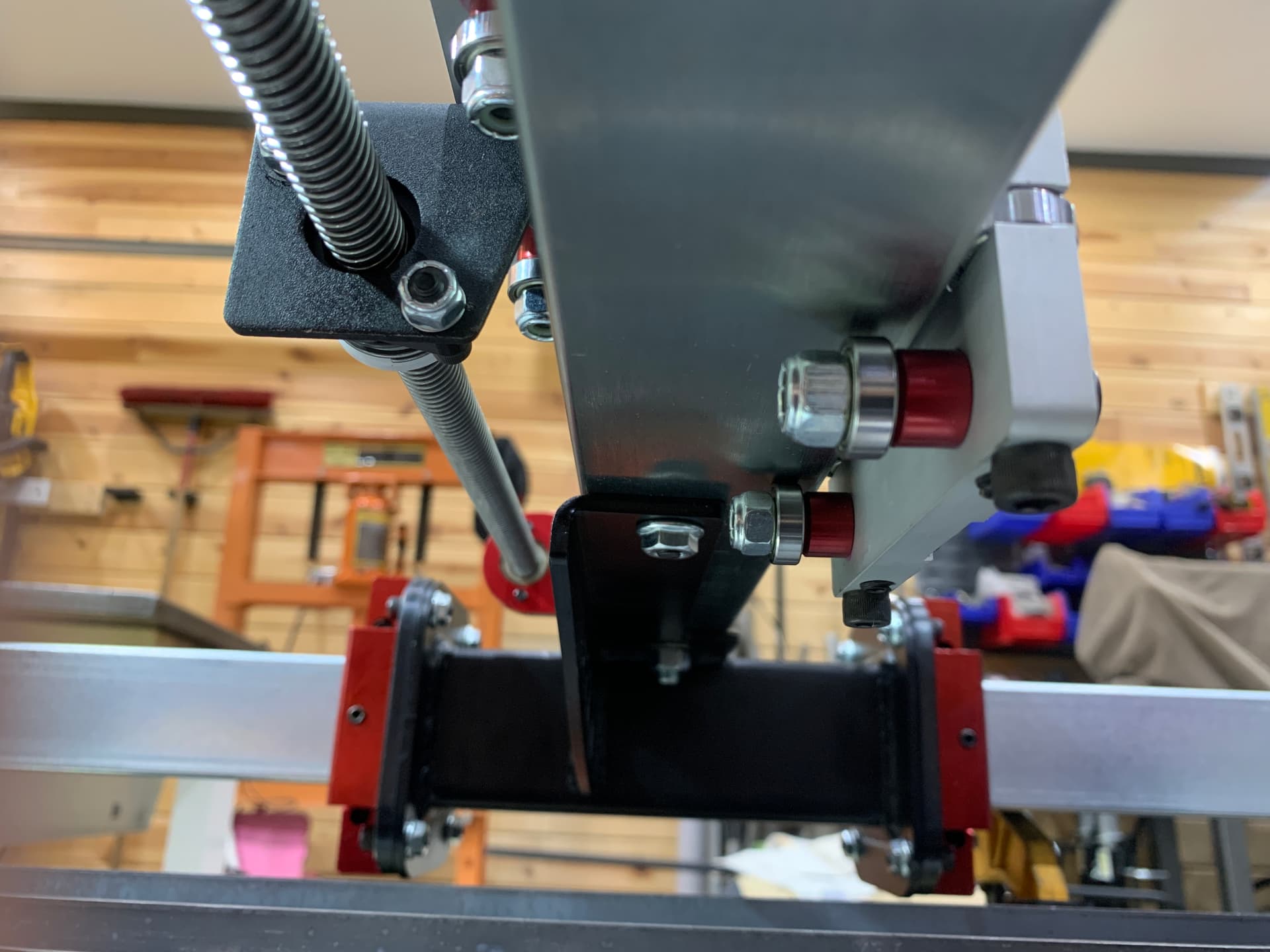
Long view from the back side of the table and slightly above the issue…
If I remember correctly, there is a lot of play in the holes on the X axis rail. You should be able to loosen all of the bolts and push the X rail further away, so the nut doesn’t hit.
Probably. But those bolts also lockdown the squaring of the X-axis to the Y-axis rails… and I think to do that properly I would have to remove the lead screw assembly that I just put on there??
The X axis motor and leadscrew assembly are bolted directly to the rail and will move with it. Yes, you will have to check the square to the Y again, but it won’t affect the motor or leadscrew.
You can move the Y axis assemblies without removing the leadcrews. Without holding power on the motors, you can turn the screw by hand to move each one independently.
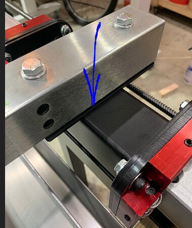
should be square if you align the top rail with the edges of the carriages where i marked in red. that should give you enough room for the x axis to travel fully to both sides.
The first time you set up the X-axis and square the brackets, the instructions tell you to move the rail through the entire range of motion to make sure there is no binding on either side. If you leave the leadscrews installed there is no way to perform this check and get a “feel” for how smoothly the X axis is moving on those Y-axis rails.
It’s a bummer if I have to take all thoes leadscrews off to get this corrected. It took a LOOOOONG time to get them threaded properly last night.
@TortillaMan Hey Greg,
I think you may have an adjustment issue here…not a design issue…
with thousands of tables sold…and this is the first time in any forum I have heard of this…and I have been here for 2 years and was one of the first batch ot tables out…
is this was a design issue it would have surfaced before this I think…but let us hear from the experts…
No disagreement here… the quality of this kit has been really nice, and I haven’t had to do any weird filing or hammering of parts to get things to fit. It’s all been going together really nicely.
Here are a few more photos that might help…
This is from the front of the machine looking at the right-side mount. The black bracket sits maybe 3/32" to 1/8" out from the square tubing… perhaps if there were flush I’d have adequate clearance underneath.
As @ds690 mentioned… this might just be a simple issue that there was extra clearance in the mounting holes of that support bracket and it was just too far offset to one side when I got everything torqued-down.
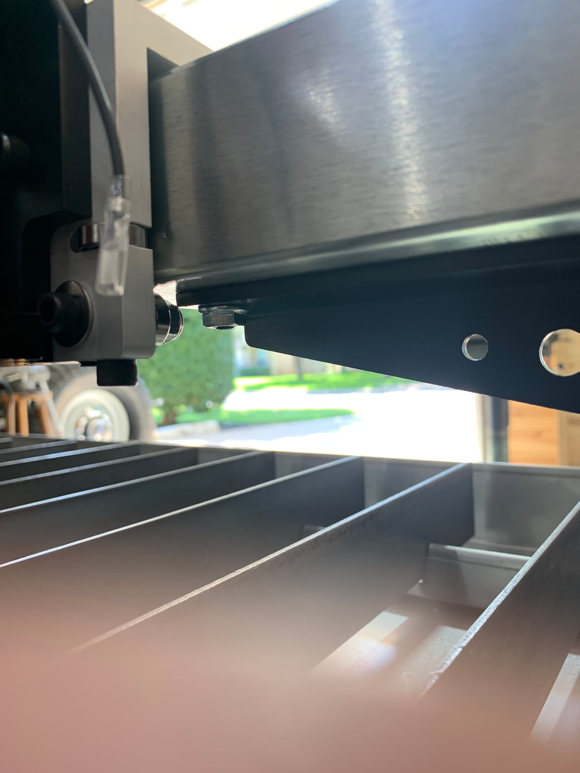
Maybe these extra photos will be a good comparison to others that are working without any clearance issues.
I couldn’t just do it the “easy” way loosen the bolts, it just felt like there was some kind of binding or resisitance in the carriages and they didn’t want to align perfectly once the main X-axis beam bolts were freed up. So I spent a few extra minutes and pulled the lead screws from the each side, and loosened up all the set screws and cap screws on the bearing blocks so that there would be complete freedom of movement to get the upper rail nice and straight.
You can see the witness marks from the original nut location and there was maybe 1/8" worth of extra clearance available within those bracket holes. Now I’ve got plenty of clearance and everything looks a lot better.
NEXT QUESTION:
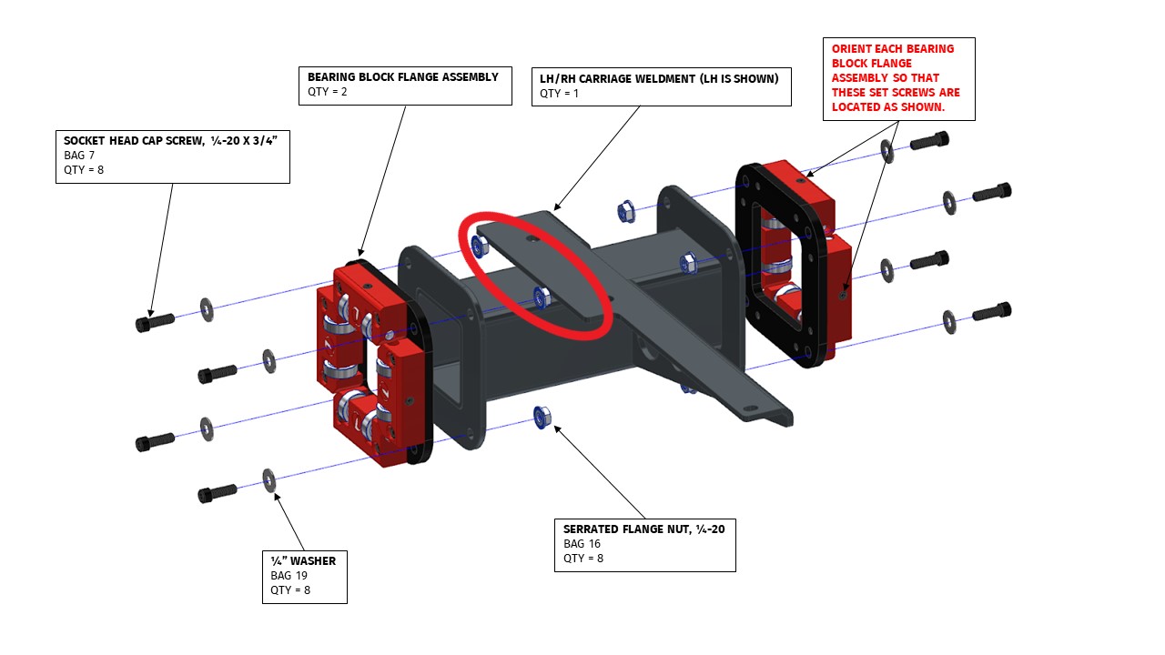
Went back through the adjustment sequence for the side bearing guides. Initially, I had loosened the end plates (stanchions) and the 4 cap screws on each sub-assembly… then loosened the cap scews on the bearing blocks themselves (and loosened the set screws). From that baseline, I would wiggle the assembly up-and-down to observe and hear the clicking of the bearing clearance between the bearings and the rail… slowly tightening the set screw as I moved the assembly until I could just feel the bearings touch on both sides of the rail (and the clicking stopped)… then backed-off the set screws by about 1/4 turn and gently firmed up the cap screws on the bearing holder. Did this for each of the horizontal and vertical blocks.
My objective was to make sure that at least one bearing in each block would roll when the rail was moved along the side tracks, and this technique seemed to work pretty well for that… I didn’t have any “floating bearing blocks” where neither bearing was touching at all, and that seemed to be the objective based on the Languir instructions.
Now, the overall effort to move the Y-axis rail along the two X-axis rails now seems a bit stiff. It DEFINITELY does not just coast along easily… and also can not be moved gently with a finger or two of pressure. It takes a steady hand pressure to get it moving and will come to a stop immediately when force is removed. It doesn’t feel “stuck”… but it doesn’t feel buttery-smooth and effortless either.
Is there any rule-of-thumb for how much drag is acceptable? I realize that the idea is to strike a balance between leaving backlash in the bearings (which can lead to cutting errors) and making it so stiff that the motors are really struggling to move the rail foward and back.
You want it to move freely, the motors will bind up and stall if there is too much resistance. You probably noticed that the bearing blocks get tighter when you tighten down the bolts. You have to leave the set screw a bit looser than you want, because the bearing block will tighten up when you tighten down the Red block.
I appreciate the suggestions and it seems to be working better now… but I need to go back and re-do the bearing adjustments because it appears that I have them WAAAY too tight currently.
There was enough adjustment in the brackets to move them over as everyone suggested. It worked fine after that. I also went back and loosened up my adjustments on the gantry bearing blocks which were set too tightly… everything has smooth movement and complete travel now.