I am making my laptop stand and I had to edit the font on my logo some so the letters don’t fall thru but when I go to extrude the part, part of the letter B and R aren’t extruding. You can see in the pic that they are grey, can anyone tell me why? Or how to extrude those parts.
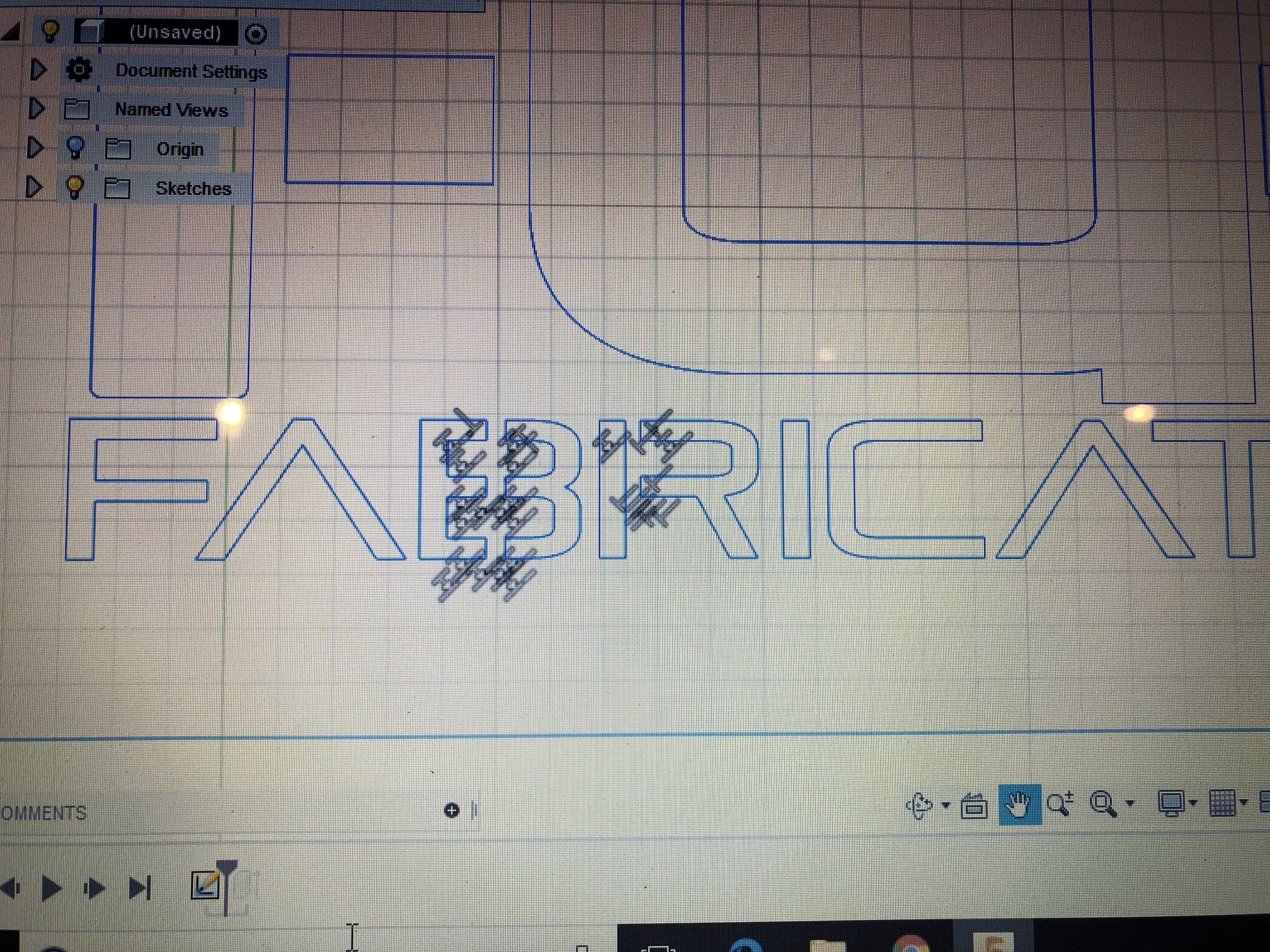
Good looking logo. My guess is that the parts of text that arent extruding are actually open loops. If you open the sketch back up, zoom in and see if theres any segments that arent connected.
3 Likes
Well Daniel i went back and zoomed all the way in and didn’t see anything that wasn’t connected. If I connect the lines then it will extrude (but if I go to cut it like this, the letters will fall thru) got any other ideas?
I would create another sketch to add the connectors for the ‘B’ and the ‘R’. Sometimes its easier to do a second sketch/extrude versus figuring out where the open loop is.
3 Likes
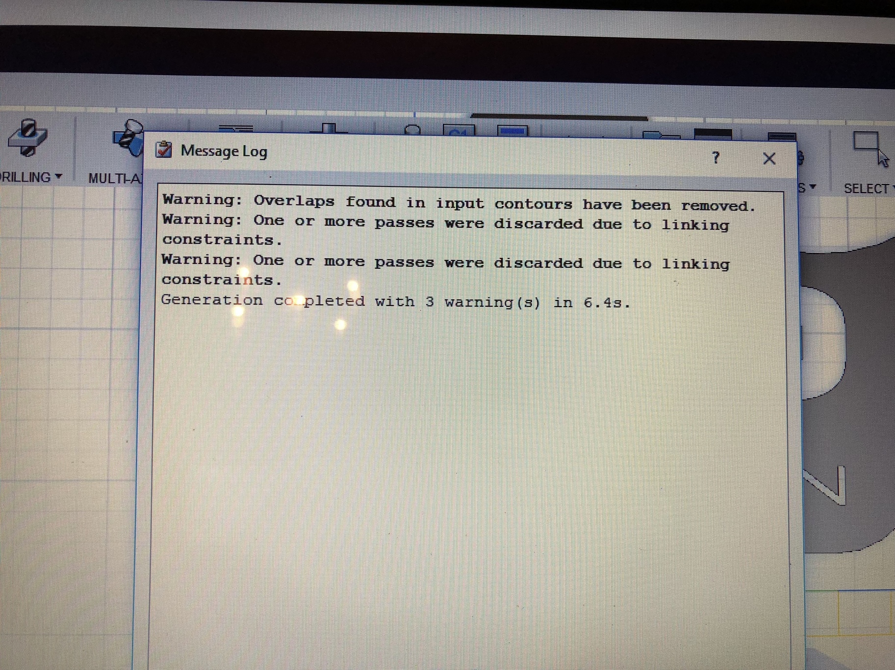
Alright I was able to fix that issue, but now I went to post process the part and after selecting every piece that I want to cut out, I notice that when I go to simulate the cutout it doesn’t do what I selected, even after making it a g code and uploading in Mach 3, it is not anything like my part. In the pic you can faintly see the blue and yellow lines under my part. Any info on what’s causing this?
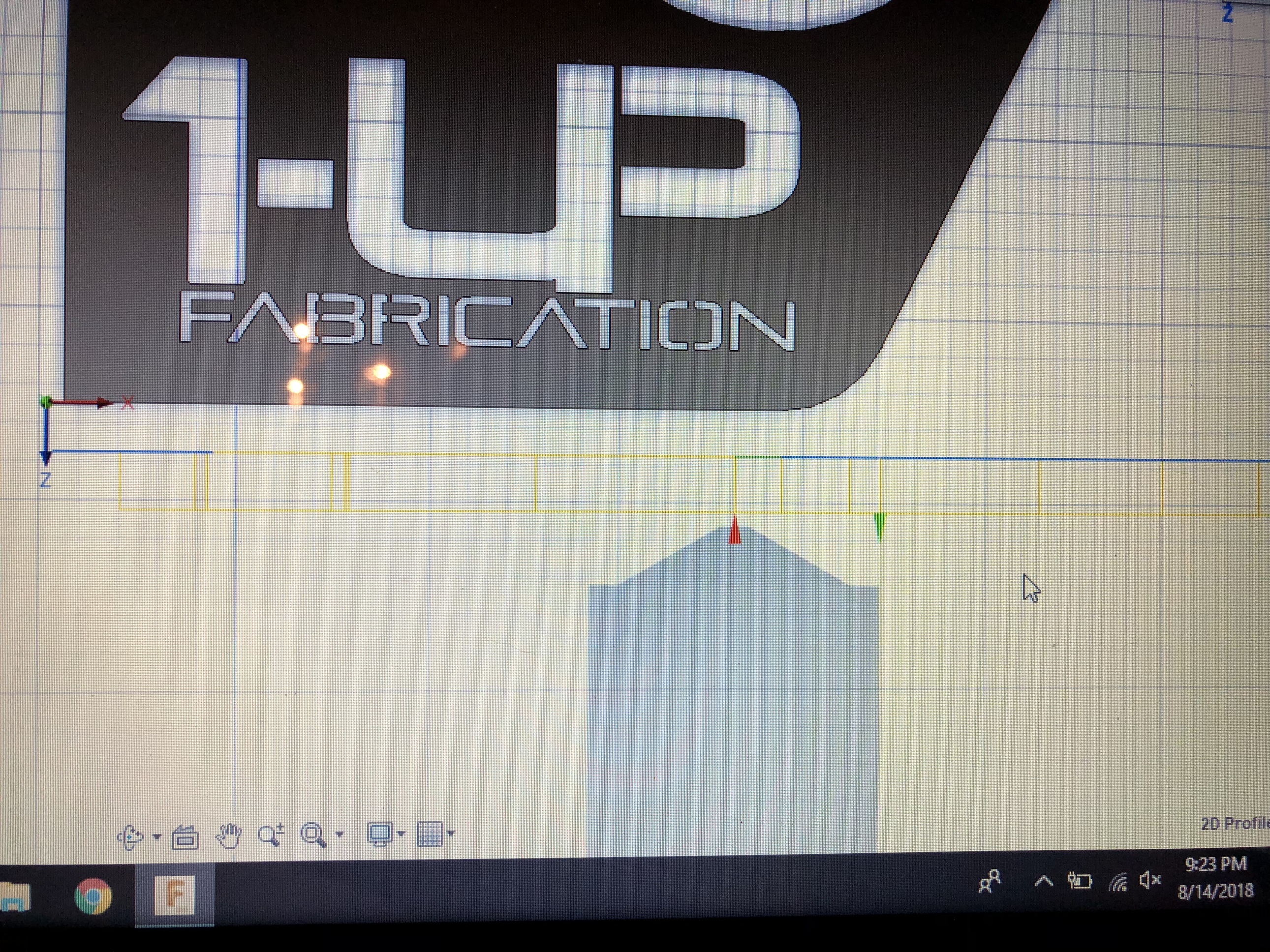
It appears that your coordinate system is incorrectly oriented. You need to have the Z axis oriented perpendicular to the part.
Check out video 3 in our CAM video series: http://www.langmuirsystems.com/tutorials
2 Likes
Alright Daniel I will give that a try. I honestly didn’t even do that step as I was just doing step by step per the Langmuir instructions not the Langmuir how to videos.
You can change the CAM Setup coordinate system without changing your sketch. You may want to show the origin coordinate system in the CAM project tree so you can specify project axes during the Setup.
This was very helpful, thank you!