I envy you guys! ![]()
1 Like
I think you can change the file ext and upload that way
When I read some of the posts I feel like there is going to be a cnc mill show and you are all going to be judged on fit, finish and over all detail. ![]()
2 Likes
Good call on the filetype. 3d print file attached.
drain fitting temp cover change to stl.dxf (262.2 KB)
Somewhere out there is a shop teacher ready to critique everyone’s work haha
4 Likes
Any chance i can talk you out of the height from the drain top edge to the mounting tabs. So basically how far below the top ofthe machine tray the drain sits. Im going to build my own coolant system higher preasure and in tern more volume to evacuate chips in pockets. So want to build higher volume drain.
Thanks alot cant wait to get mine
You read my mind lol.I literally thought about this last night.
Change file extension to dxf and then we can change back after downloading.
I’m slacking behind all the other builds. I got the whole mess unloaded and the drain covers printed. Woot
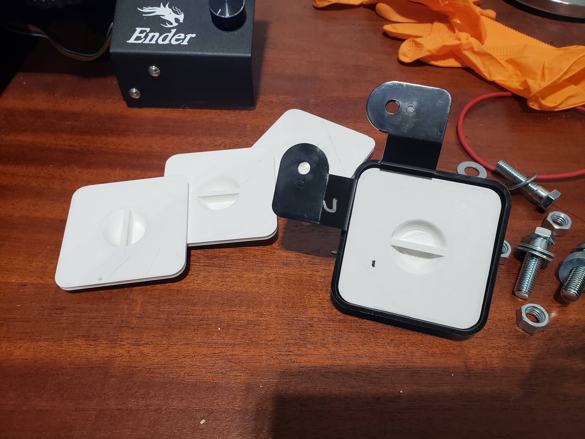
6 Likes
Nice job.That will ensure you don’t get any epoxy in the drains. Geat idea.
Ill be printing these soon.
Did the 3d printed covers need supports? I will be printing them soon. Thank you.
No supports required. They are drafted and there is a little bridging that occurs at the bottom of the finger holes but mine came out good enough for what they are.
1 Like
Thank you so much, will be printing them today. Want to be ready when my MR-1 gets here.
So life got in the way but I’m finally back to work on this thing! I may take over the slowest build award haha.
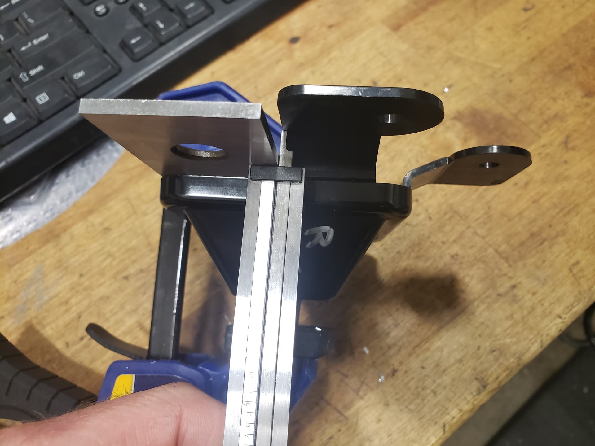
I took one of the base plates into work and added a bore with a counterbore and o-ring groove. I wanted a pass through specifically for machining the ends of axles. I have an aluminum cap machined also.
I modeled a 3d printed spacer that leaves 1/4" of concrete to be broken out later. TBD how well this works.
Four studs will be embedded, sticking down below the table after the pour. These will be handy for a steady rest or future fixturing I think.
I’m catching up on the other threads and I am contemplating some coolant drain modifications before I pour concrete. Others have mentioned drains clogging and I have been toying with a chip auger design. I bought this 2" hole auger (amazon) but it hasn’t arrived yet.
My plan is to embed a 3" tube with fabricated end caps now, and build out the rest later. CAD screenshot shown below. Perforated section with a chamber below, and a large drain tube connection.
Question: To those of you with completed units, do you see any conflict with where I placed the auger?
A few progress pics:


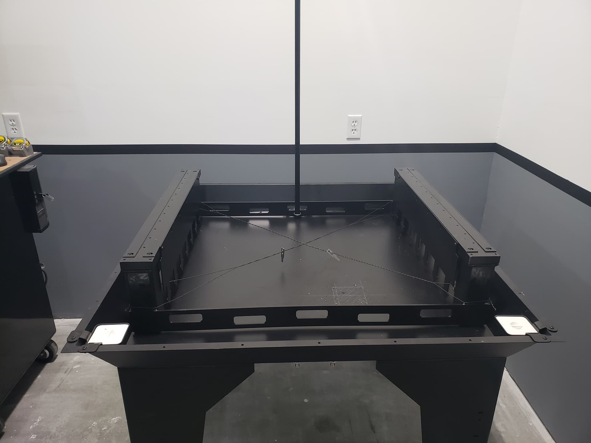


3 Likes
this is awesome. Is the chip auger at front or rear? If it’s in the rear I suspect you will might have issues with cable support. You should be able to squeeze it behind that, I’d recommend setting it up on a slope with a 5/8 or 3/4 drain or put a 1/2’ drain on each end and just do away with the stock rear drains less stuff to fuss with during pour. Make sure you mount it well for the pour, when you start tamping it can push your drain towards the surface, I would secure it with some studs through the bottom. Also awesome pass through, I was just going to core drill mine if I ever had the need.
It’s at the rear. The stock rear drains would be eliminated.
I’m still in the planning phase but I think I’m going to cut and weld the whole thing in. No chance of it moving then.
sounds like a good plan, Might aswell do away with the concrete between it and the pan edge at that point or just push it all the way to the pan edge. Are you going to put the motor below the water level or use some kind of u joint linkage and remote mount it? Also re thinking it, I would put a good slope on it like at least 1/2", more if you intend to really pump a lot of coolant, on the coolant end use a 3/4" drain and then on the high end use a 1" or 2" through hole and have the chips dump in a bucket under.
The current thought is to add a bearing and mount the motor outboard on the far end. The near end will have a 3" tube turn up and then an exit chute into a drum. Similar to most other CNC machines.
I’ll update the model and post some more screenshots as I go. For the moment I’m trying to get the provision in place and then move on to general assembly. I can put gaskets and blank covers on for now and come back to it later.