Not a dumb question. I dont but also theres times where you can have more material on the bottom do your whole op full depth cut and then flip it and face off the extra material.
I also want to ask when you indicate off your hole do you indicate off the same side of the part when you flip it? So hole in in the middle | 0 | you touch off on left side do your mill op and then flip it. Do you touch off on left side again or right side?
I indicate the center of the hole using a center finder on both op1 and op2
Gotcha ok that rules out concentricity of the hole. I am gonna hold true that the material is not square enough for a flip without either squaring the material or doing a side indication and not using the hole. Indicate off the side that touches the stationary side of the vise then flip and indicate off the side that touches the moving part of the vise (ie the same side of the material).
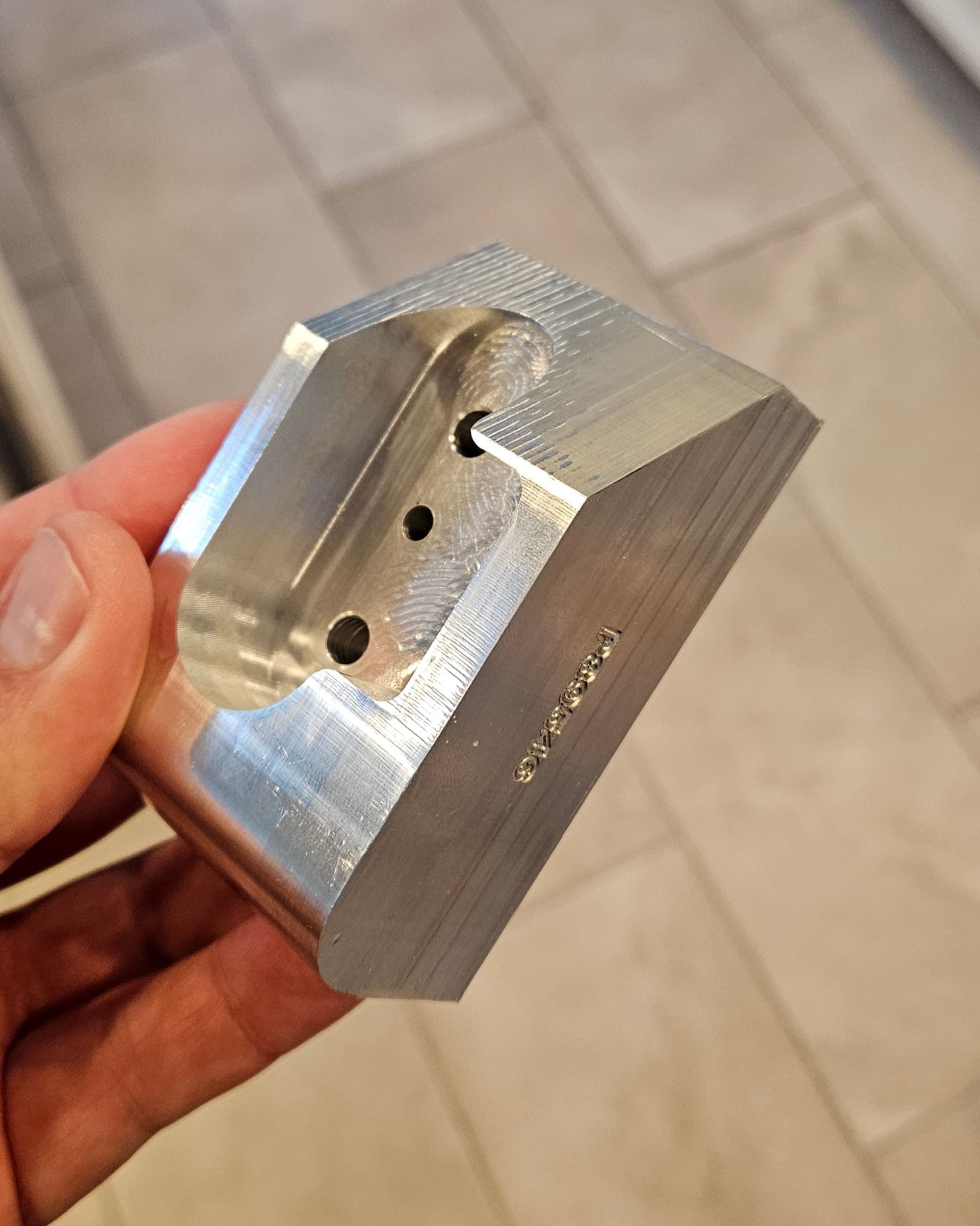
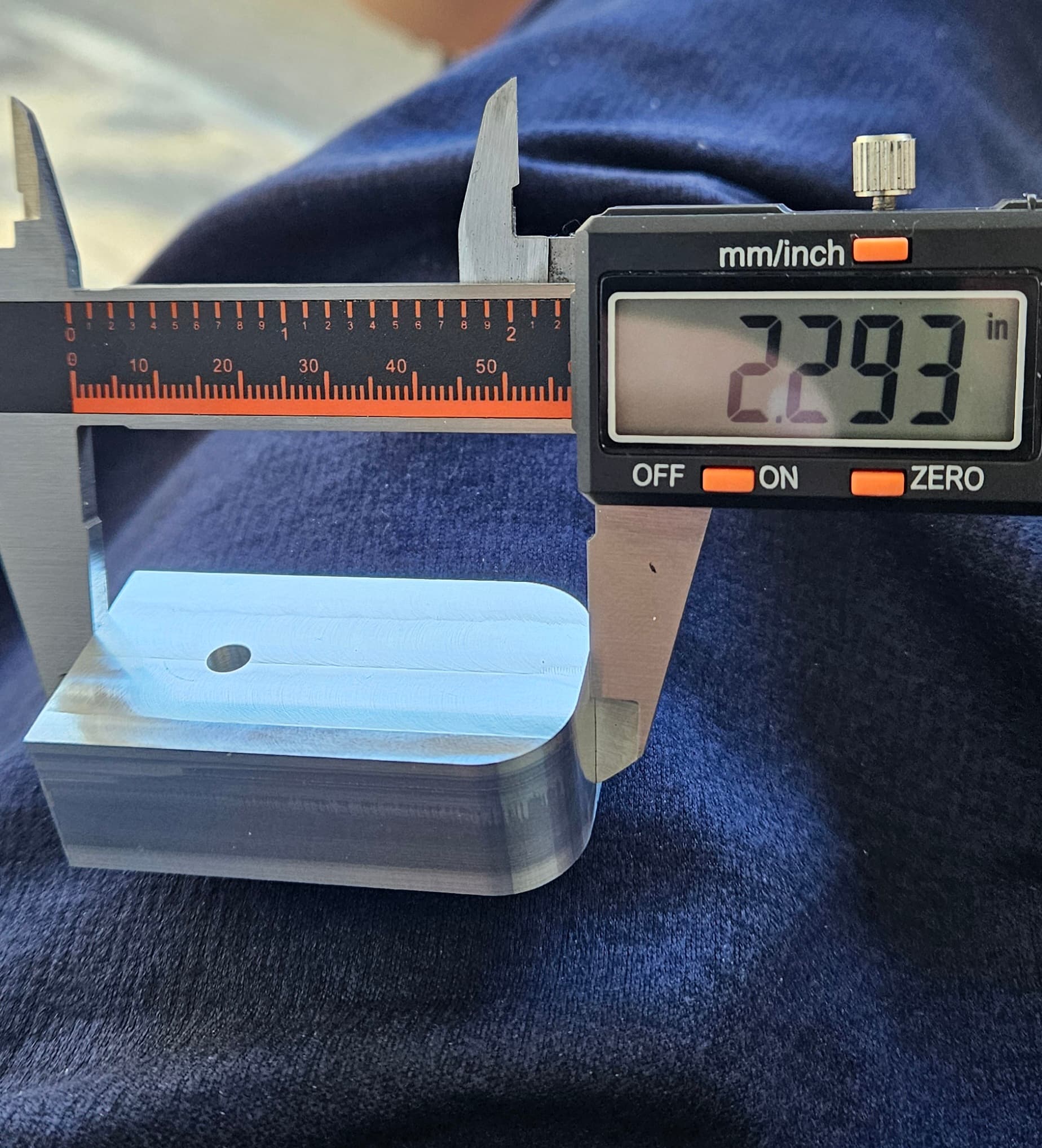
So i have solved the two side flip problem! I squared up all the edges first. That did it. HOWEVER, now I have an even bigger problem i need to solve…. This part is supposed to be 2.25” long, and it’s way off.
But both OP1 and OP2 cut identical, so its something in my CAM? In Fusion360 it says the part size is 2.25…..and even the setup sheet says that. What would be causing the MR1 to be cutting so off distance wise???

Glad that you got that figured out. Over is better than under, i would say side load on the mill. Someone who is better at feeds and speeds will need to chime in. You can also just adjust the offset manually. I am interested though. How far off is the hole to the left side edge (non rounded) is the hole the correct distance? Basically trying to see if one side is long than it should be or both are. What about side to side measuement?
.043” too big is a huge offset. I would expect you to easily be within 0.004” and then to have to chase down to 0.001”-0.002”. I expect there is something hiding in your CAM operations, like the option to “Leave stock”. Check your simulation, does it go right up against the edge of the CAD model?
1 Like
I think i found the issue. Even though I’ve set my travel compensation many times in cut control it was way off again. I had to recalibrate and it took a full windows restart for it to “stick”. I set it probably 4 times before it finally took
So they changed the test part… Interesting. I tired to make the test part about 8 months ago and it was different. Either way they always design it in a way that tries to force you to flip the part. That weeds out people with low cost machines like the MR-1 98% of the time.
The Amazon link I sent was a 4” long endmill…
here is a 6mm endmill that is 150mm long Carbide Radius End Cutter Mill Aluminium Cnc Milling Cutter For Metal Tungsten Steel CNC Maching Endmils - AliExpress 1420
when I was doing my Xometry Part I purchased one of these that was 75mm long. My problem was flipping the part and still having the dowels within tolerance.
@Richarddbeck83 what is a bigger machine going to have that the MR-1 doesn’t in terms of part flip repeatability? Same vise technology… possibly more accurate probing but I think that’s still debatable as the v2 probe is now on par with conventional edge finders.
1 Like
I dont think flipping the part is really that big of a deal. What was the original part you had to do if you dont mind me asking? If you could post a pic that would be great as well. The MR1 seems very capable considering what it is and priced at. Biggest limit i see is the Z height, its gonna make machining pistol slides interesting, having to figure out how to come down on the end to bore out the barrel and guide rod hole.
I think i can make the part now no problem….I’ll try in a day or two and report back here. My issue was definitely not having square stock and my travel compensation being off
1 Like
A professional grade machine will be able to probe within .0002” its rails will actually be flat and its axis will be perpendicular with each other. it’s axis are closed loop systems with precision ground ball screws. Some professional machines will also calculate thermal expansion and add that into the distance calculation using thermal couples in the spindle.
Sure the MR-1 can make beautiful parts and bore small holes that are very accurate but cut a part that is 18” long and measure it’s overall length flatness and squareness and you’ll see it’s pretty bad no mater how much time you spend dialing it in. That’s why I stick to small parts, or design around the MR-1’s limitations. You can design assemblies that don’t require perfection.
For example: At the day job I can design a part with two press fit dowel holes 50” inches apart and have its mating part also have two dowel holes 50” apart and the two part will fit together. on the MR-1 if I have two dowels that are 3” apart I need the mating part to have a hole and slot on it. The hole gives me X, and Y location, and the slot will limit rotation but allow slight mismatch between parts. I still get a great assembly that works really well, I just have to design things within the MR-1’s capabilities.
1 Like
Not trying to start an argument, but my experience (mechanical design engineer, the MR1 is a hobby for me to be kinder to my machinists) is quite different… per your example… maybe if you make both parts on the same machine in the same place with the same fixturing with reaming tools, but unless you are rocking a DMG Mori, I think a Haas (arguably the most common industrial mill in the US) is going to struggle with what you just described. In my current work environment, I’d get laughed away if I showed up with two dowel fits 50” apart without any slotting or tolerance allowance.
I don’t work in aerospace or precision, but instead in consumer products/industrial. ±0.002” is considered a really tight tolerance… it’s everything I can do to get parts in qty with a Cpk over 1 that are within ±0.004”, especially from xometry shops.
1 Like
We do have a large Kuraki at the day job that’s really good. I would agree I wouldn’t do a full 50” unless I had to. Could that machine pull it off? It’s possible… We had and old timer running it who was mind-blowingly good. I guess I’m not saying it’s a good idea but with an expensive machine it would be possible. On the MR-1 I don’t bother trying to do two dowel holes ever… I just do a hole and a slot.
Another major advantage to a professional machine would be the collet options and Z travel distance. I’m not trying to poo-poo on the MR-1. I love mine. I’m just explaining why I would outsource some jobs to a shop with professional machines.
Even a small machine with a BT-30 spindle could run shrink fit extended reach tool holders. That would allow you to get deep into cavities and machine things the MR-1 could never touch.
I might give Xometry another shot in the future. I tried the test part 7 times (never sent it in). The 7th time I was down to one of the last operations and the MR-1 missed a step and messed it all up. On the bright side the process of trying to do the Xometry part got my MR-1 really dialed in. I spent over a week tweaking everything as much as I could. I also stepped up my inspection tool collection during that process which still benefits me now. Since than I’ve upgraded all my motors and power supplies to ensure I don’t miss steps. There is a chance my current MR-1 could now make the Xometry part.
I did call and talk to Xometry when I realized I couldn’t hit the test part deadline. They said no problem. They just put a note on my account that it’s on hold.
@Richarddbeck83 if you wanna give the Xometry test part a shot, I have attached here. I still cannot get it within tolerance on the MR1. I have tried probably 5 times. I get close…but always off by about .005” (from tolerance) on the profiles… I am convinced the MR1 is not capable of making such part to required tolerance. Would love for someone to prove me wrong!
Xometry_Mill_Test_Part-1(1).step (80.6 KB)
Xometry_Mill_Test_Part.pdf (51.6 KB)
1 Like
I wouldnt mind giving it a go, ill have to order material first so itll be a few weeks. What are the tolerances on the part?
Edited to add
Im an idiot there was a pdf file with the info
1 Like
So this is the same Xometry part file that I currently have. I thought maybe they changed it. Part of me doesn’t even want to submit it with the MR-1 as my only machine because if it takes me 8 tries on the test part can I actually make money on their real parts?