Having trouble getting nice holes

Its possible your consumables are worn? Or perhaps your travel speed is a smidge fast? These are the things I’d suspect

There is always going to be some angularity. Probably where it seems better is the portion of the hole where it first started? I find that if I have small holes I make a separate tool path with a little less speed and that seems to help. Mostly I make them undersize and drill them out after, especially if they have to be taped.

1 Like

IDido.
I always under size the hole with the cutter then finalize it with a drill bit .
Anything under .250 “ I’ve never been able to get the crossfire to cut holes anywhere close to circular.
Yes I’ve checked and adjusted everything…
.500” holes and up are no problem

See this post: it helps with smaller Small holes issue

1 Like

I have tried slow, and new consumables. The holes range from 1/2” - 1” and they are not what I would call acceptable. It’s got me thinking I have got something set wrong?

Are your lead screw setscrews super tight? It may be shuddering a bit as it comes around the curves - just a tiny bit but enough to trash the hole.

Can you post a pic of your holes?

1 Like

Here is a slug I had laying around from one piece. Gives you some idea.

Based off both the long sides being beveled I would say your torch isnt perpidicular(90 degrees) from the material being cut. I had this same issue till I re adjusted and I am happy with the results.

Plasma cutting good quality holes requires a height control and a good quality plasma system. If you are piercing at the plasma cutters suggested cut height…then expect the nozzle (some call it a tip) to be damaged as soon as the very first pierce. The nozzle orifice shapes the cutting arc into a spinning, rotating column of hot, ionized gas (as much as 25,000 F with an air plasma). The arc relies on the accurately machined copper nozzle orifice to control its shape, however when a crater or a nick is formed (from piercing too close to the material, blown back molten steel will damage the copper nozzle) the ionized gas arc changes shape and affects cut edge angularity. To get thousands of starts out of a plasma torch nozzle you must pierce at the recommend pierce height, staying in that location with no x, y or z movement, then rapidly index down to the recommended cut height, then start the x and y motion. The correct pierce height directs molten metal away from the nozzle orifice preserving iuts ability to keep the arc straight. Indexing to the correct cut height after the pierce gets the “sweet spot” of the plasma arc properly positioned in the materials to produce the best quality holes. Air plasma holes will always have some taper, however they can be round on top and bottom when pierce height and cut height are maintained as the plasma system manufacturer suggests. (I worked for Hypertherm for 41 years…just to reference my experience here!). Here is a pic of various holes cut with proper height technique with a Powermax system operated at 45 amps, shielded mechanized consumables on my home shop machine. To allow a 1/4" bolt to drop through a plasma cut hole, you must size the bottom of the hole (increase the top diameter accordingly) This is 1/4" steel. Top numbers are the desired hole diameters, bottom numbers are the measured top and bottom diamaters.
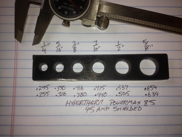
dimensions

5 Likes

Slugs or drops will have more taper then your actual piece because of the nature of the plasma arc.

But the taper should be consistent. The taper on your slug it essentially parallel with the other side which leads me to believe that the torch is misaligned or the tip is bad.

This has been an issue for me since my crossfire showed up last year. Within the last week I have been playing with the program more. I’ve cleaned up my cut quality by adjusting some parameters in the toolpath setup on Fusion. While my material was only 1/8" as of most recent, I’ve definitely seen improvements. Worn consumables as pointed out before will definitely make a difference.

Update: Thanks for the tips guys. Ended up checking the height or in my case slope of the arm in the X axis. It was over 0.1" out. I shimmed it, re-aligned to the rail, and added shims to the torch holder as it was not perpendicular to the table.

The cut is much better, I figured out how to add some dwell at the start of a cut, this helped ease into it rather than pierce and go too fast on the thicker materials. I cut some 1/2" on the weekend and it turned out ok.

One thing that did happen that is a major flaw in the table is the press in wheels, one decided to pop out on me rolling on smooth concrete. Lucky I grabbed the table but water pissed everywhere. Ditch the crappy wheels and weld on some locking ones right to the tubes as I had to. My 2cents.

The threaded insert was supposed to be peened into the leg when installed so they wouldn’t do that. Someone had the same issue you did and Langmuir identified the lack of instruction/missing step in their setup document and videos. I believe they updated the doc after that and posted a how-to here for all the existing owners so they’d be aware and could go back & fix their tables. I haven’t done mine but will take care of it when I setup the Pro and can put this one on its side.

1 Like

mine was twisted when I first got mine set up… I had to play with it to get all square.

I cut my first piece last night: 2.0" OD x 0.75" ID, 0.188" THK washer. I was actually really impressed with the results: 2.000/1.992 OD x 0.740/0.720 ID. Is there a good way to adjust the programming to open up the ID holes without oversizing the model?

Change your kerf setting.

2 Likes

For some reason I cannot find any cut charts for the Hypertherm Powermax 30XP, or any 30 amp machine for the matter. I have the kerf width set at .055", which way and how much should I adjust it? Or is this purely a trial and error exercise?

It’s simple enough to determine your kerf assuming you’ve got the rest of your settings dialed in. Cut a square inside a square, say 1" inside, 2" outside. If you use SheetCam to create it, stick with the 55mil kerf. If you hand generate the raw G-Code, cut on the line (1" & 2").
Then, once it’s cut, just measure the result in the centers of the squares. The difference in the resulting dimension will be exactly your kerf if you cut on the line, and will be how much you need to change the kerf setting if you use SheetCam.

For example, if you tell SheetCam to use a 55mil kerf, but the inside dimension is 0.995, then you need to reduce the kerf setting by 5mil. Now if your inside difference is 5 mil and your outside difference is 10 mil then, either you’re not ‘dialed in’ or you need to split the difference.

1 Like

That is extremely helpful, thank you!