Please help ive been at this two days and no joy. i did actually change one slot size but not the next one so idk.
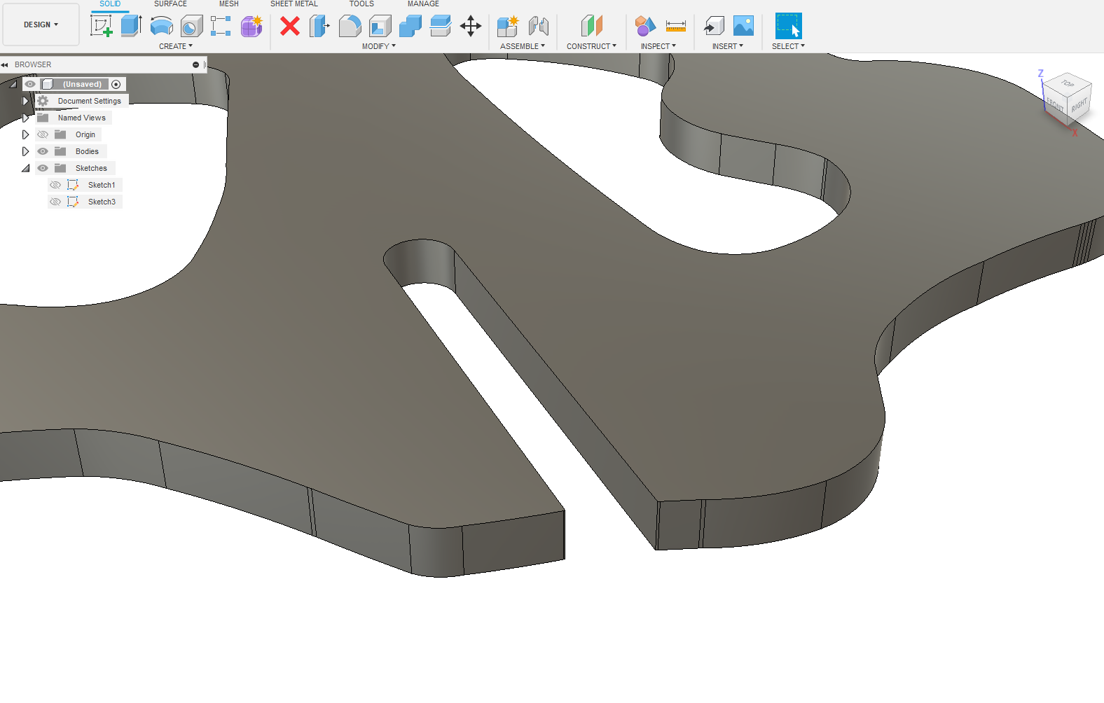
i have a downloaded cut ready file but now need to modify its parts , has slots that fit the material size so the parts can side together . THe first one i cut had the slots to small and i had to hand grind every one to fit .
Im trying to increase the slot dimension to fit different material size . Ive tried the dimension size and when i double click to add new number it only wants to change degree not distance. there must be constraints in effect but i dont see them if i could remove them or if that is even the correct way
Can you post the file?
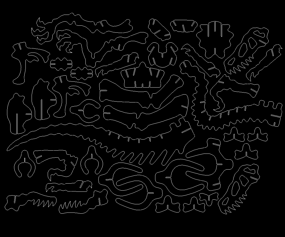
veloselraptor.nc (200.8 KB)
not sure if this will work but here it is the parts interconnect via the slots and thanks my 75 year old eyes are getting tired of this computer screen
What size and material is that?
Have you tried scale the whole project to adjust the slot width? Or is the final overall height critical? This is likely the best bet unless you want to keep the overall height/size then you will redraw all the slots manually.
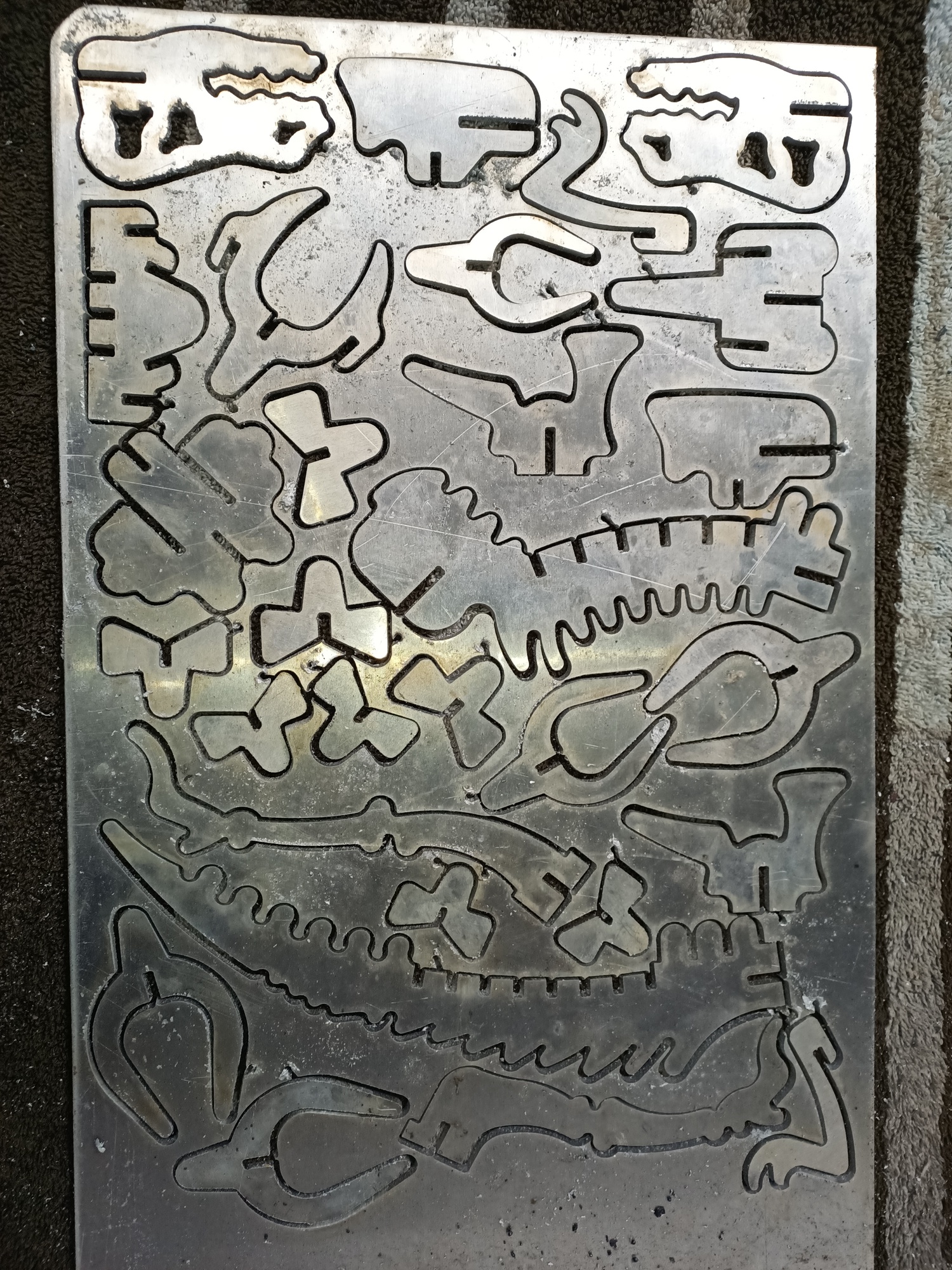
I cut a similar puzzle out back in February out of 1/8 aluminum
1 Like
I have a good price on 12ga. and made one model to find the fittment problem if i scale up 1.47 i think the size will be to big for the material . so i would draw each slot manually that is what im asking for help with . I do not know how to manipulate fusion into doing this.
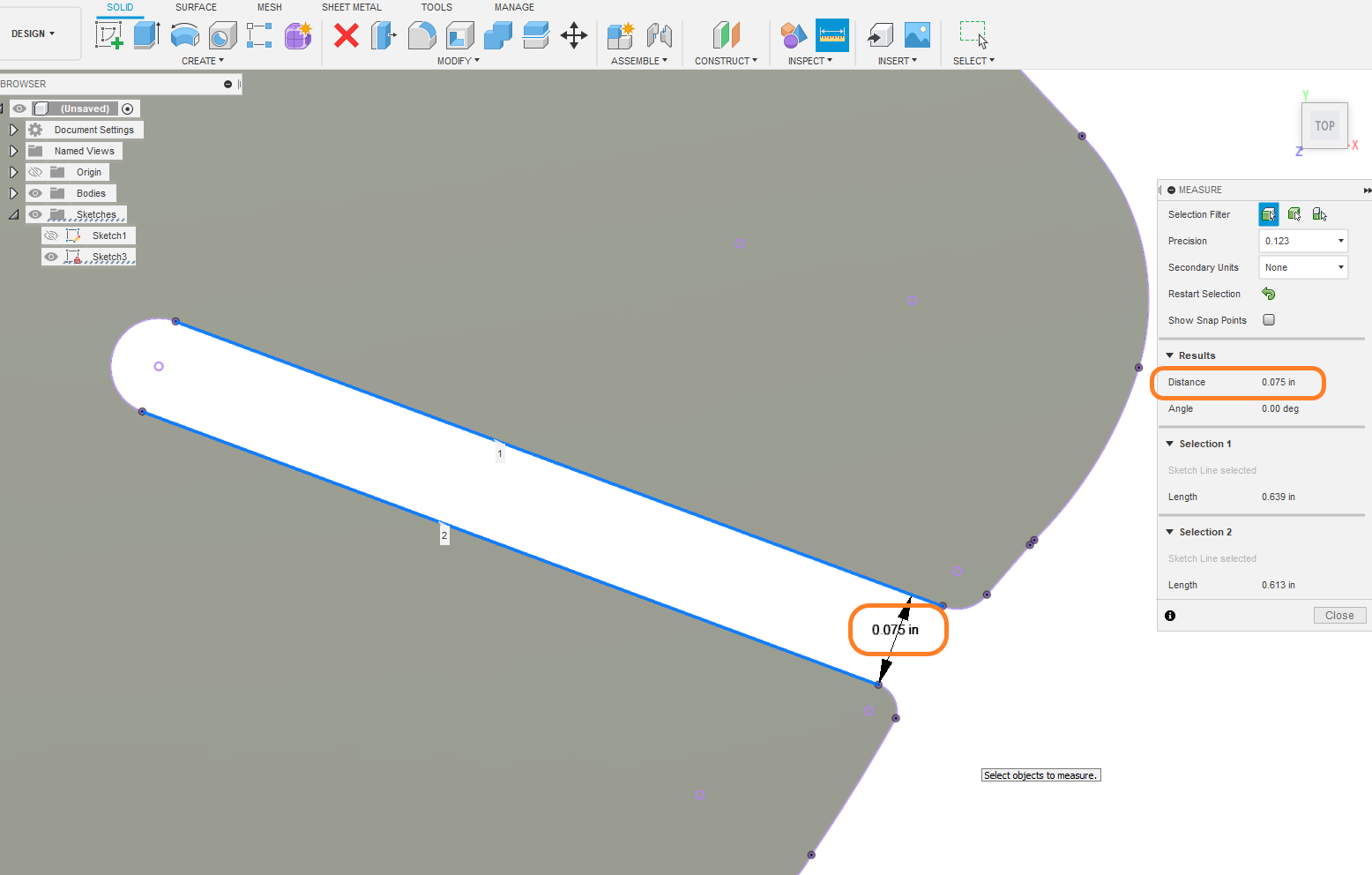
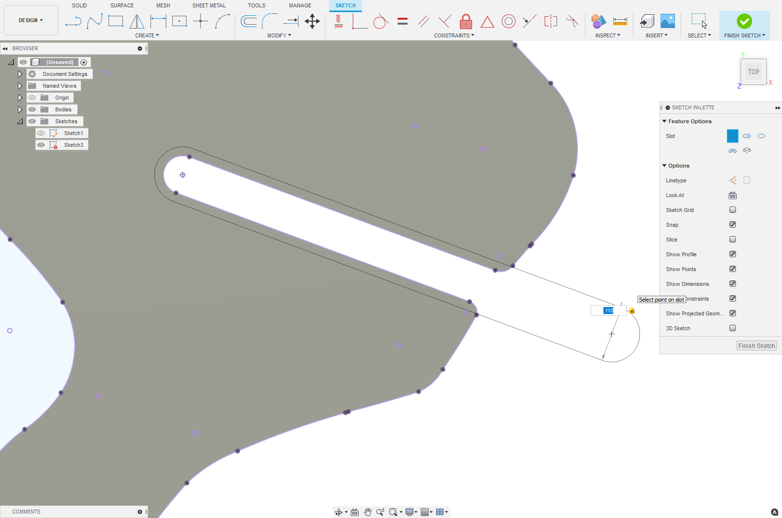
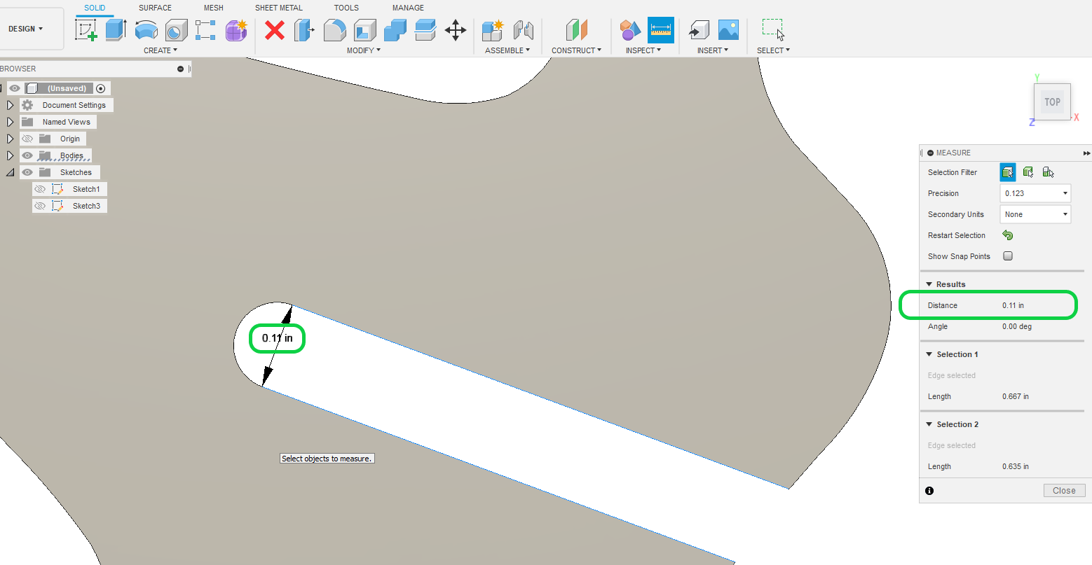
slot size is .074 and needs to be .110 to fit. fusion will allow me to change vertically orientated slots width but on all others lists the degree and not width and will not alter it so constrained some how
Scaling is by far the easiest method.
But if the doesn’ t fit the overall size of your material you could also re nest these pieces to suite the size you do have.
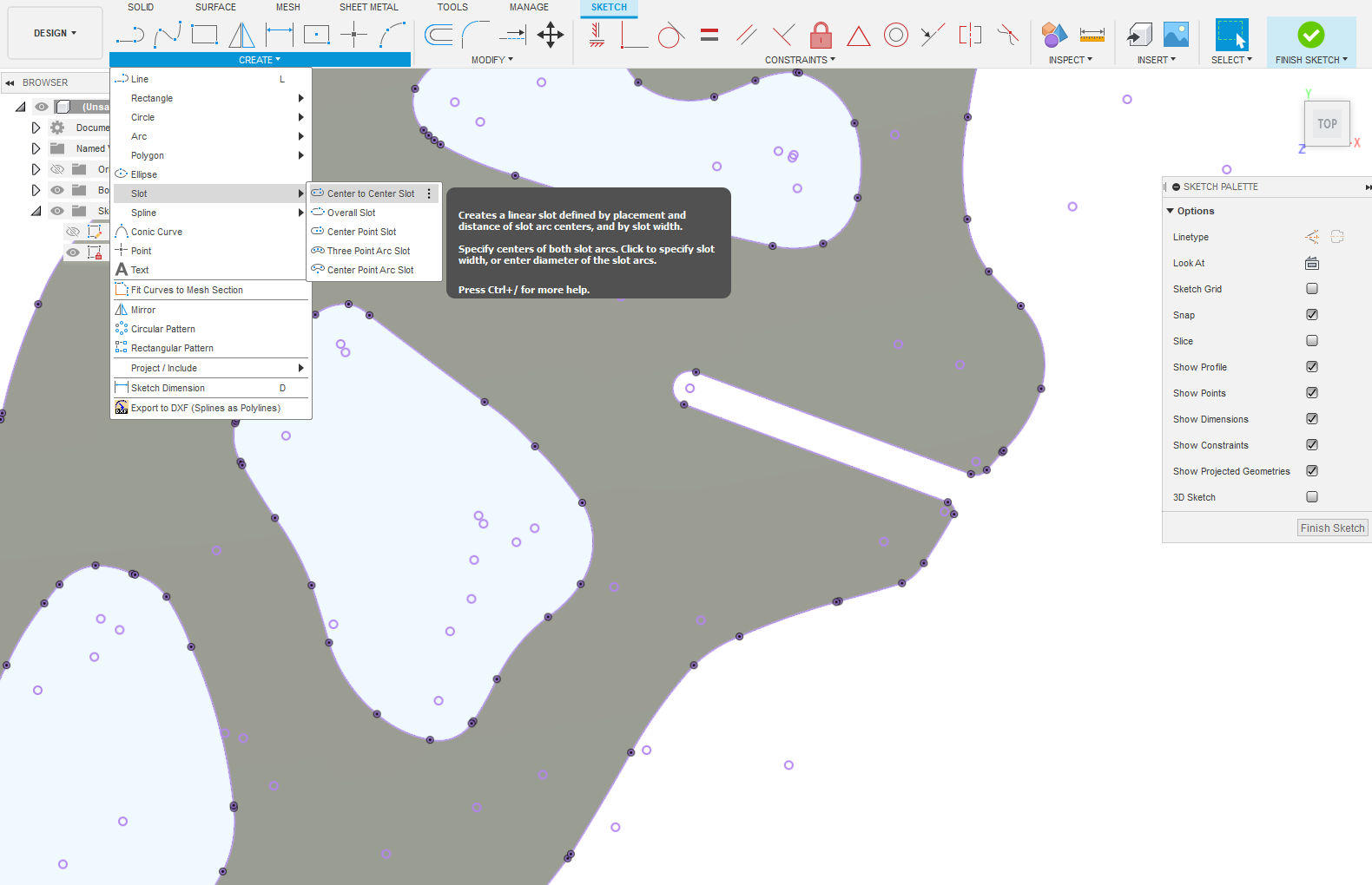
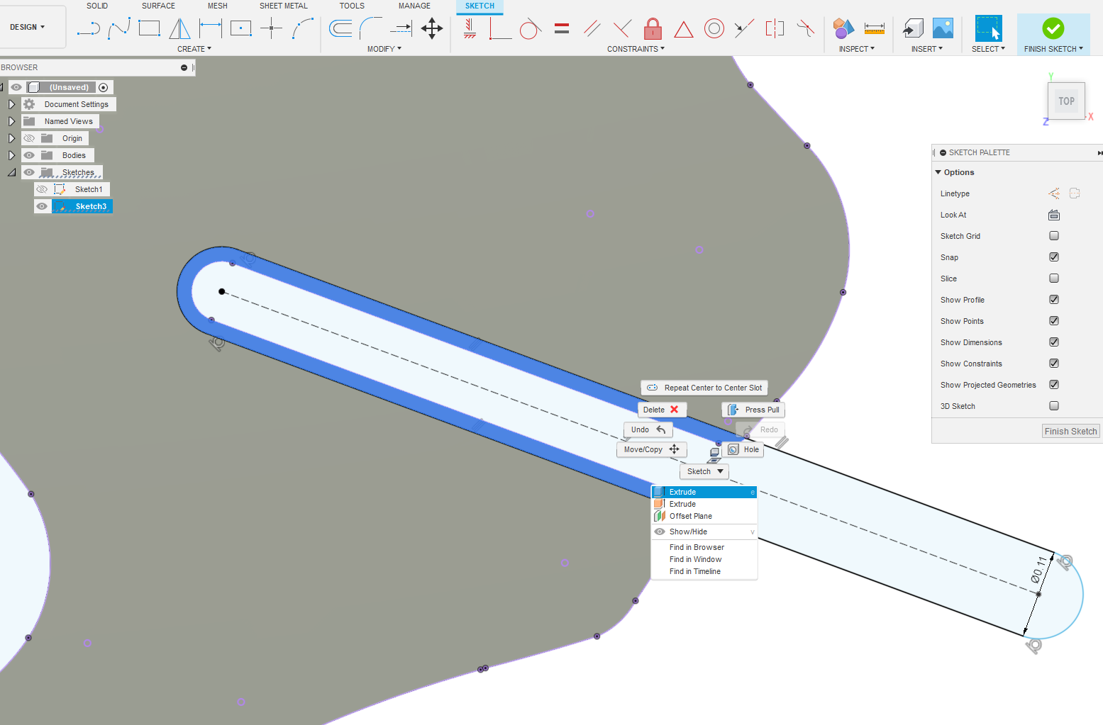
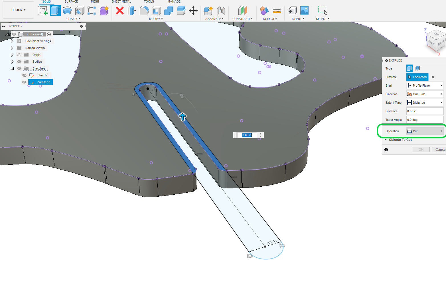
There is no simple method to resized those slots. you may be better off redrawing the slot dimensions you do want over the file and extruding it through with a cut command.
If this file had been created to fusion360 in the first place with proper work flow then you could simple enter a new number and it would change all the slots automatically.
Your file does not contain that constraint data.
This file is also very dirty and will run laggy on F360
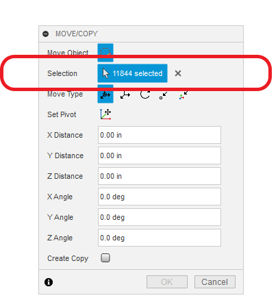
currently the slots aat 90, 180, 270, 360 degrees have editable widths but without the other constrain data changes will effect the model unpredictably.
1 Like
I went through with the slot edit and found that i could just use trim to delet the old contours . Now when i am in cam and try to select the contours it does not highlight entire shape and i have multiple arrows to complete the part so many that the entire outside is a mess of red arrows. is this because i didnt use extrude?
Yes.
Now you’re in the manufacturer space trying to make toolpaths with Sketch geometry.
This will have the effect you just described.
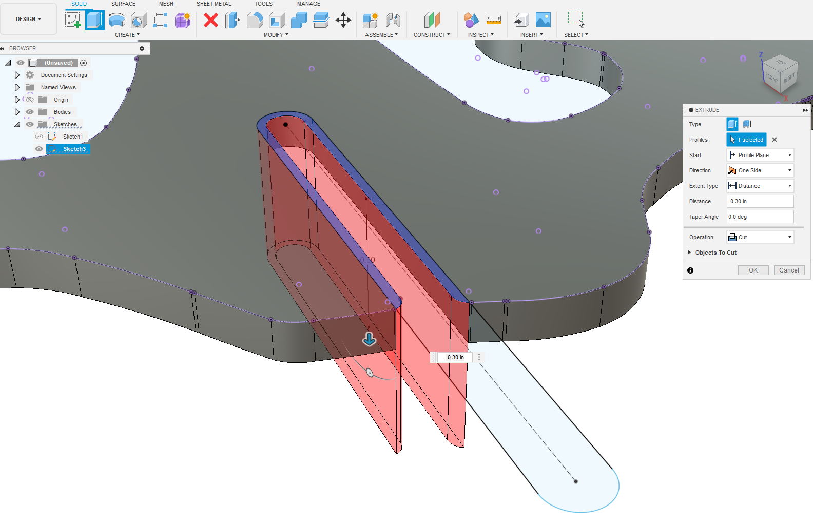
Extruding: which you could do with your new modified sketch geometry would make the selected surfaces into Bodies.
Bodies in the manufacturer workspace react differently when selecting geometries in the 2D profile tab.
There is instances where you want to use sketch geometry in the manufacturer workspace normally that’s with single line cutting.
The benefit of the method I screenshotted for you is then after the fact you could change all the slot dimensions with one dimension change if you carefully set up the constraints. Because all the slot updated geometry would have been produced in fusion and being a different sketch layer could be modified.
1 Like
There is a lot of nuance to the 2D profile development menu.
When you select you can chain those arrows together so it becomes one continuous path so it is possible to produce a usable tool path from where you are now. If you double click a line and it turns blue it’ll give you the option of a plus symbol minus symbol and a garbage can now you can proceed by holding down shift I believe and select the rest of that blue line and it’ll become one continuous line. Then hit Plus. And repeat.
Myself I wouldn’t do it this way even though it’s possible I would go back and use the extrude tool so you end up with some proper Bodies to use.
When you get to doing your actual tool paths.
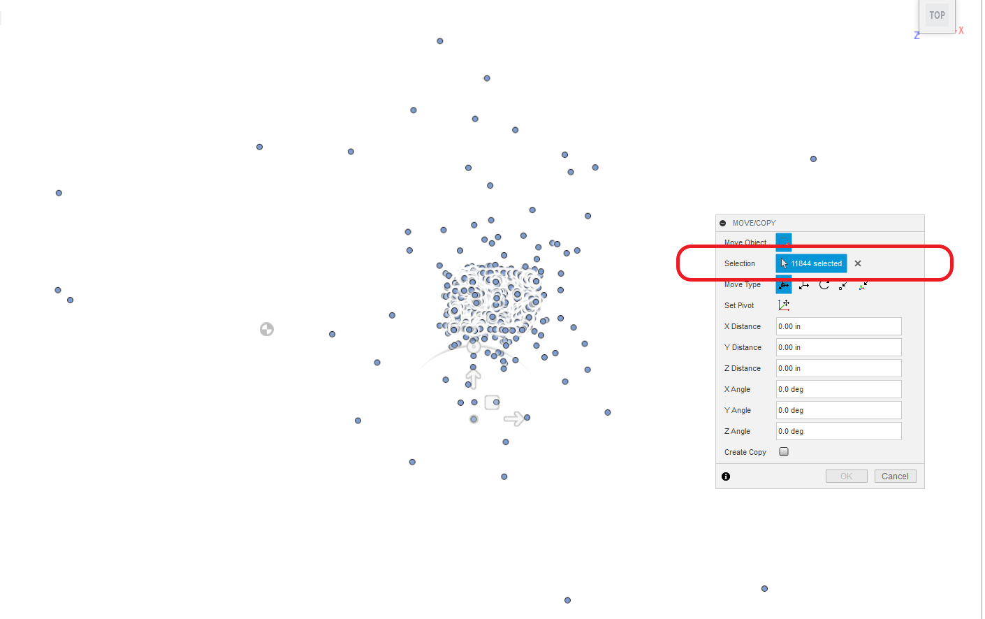
Use multiple operations for this dirty file or you’re going to stall out fusion 360.
There’s 40 bodies involved in this DXF and almost 12,000 individual sketch components.
Depending on your computer situation I might even consider creating tool paths groups of five or eight bodies for each operation.
1 Like
ok , yes you are right i do not remember switching to manufacture in my excitement to complete. Not all of the paths are broken some are normal if i have to redo i will extrude im just not comfortable with it but now im facing starting over i could have just ground out the slots manually by now . i realize the sad part is this will be for only one size scale and material each time.
Thank you so much, i had no clue still not much but as usual i have to make every mistake to learn .
1 Like
There’s an absolute huge learning curve to Fusion 360.
Constantly refining your workflow in fusion360 will make you fast in time.
The day In the future you start using fusion360 and you’re not thinking about which tools, where, how and whatnot and are just thinking about the project.
it’s pretty amazing.
At this point i’m very dissatisfied with the complexity but i have nothing to compare it to . I see that my trim has left some ends that i have to zoom in on to see hope that fixes it before i start over. or can i just extrude the parts as they are after the slots have been changed ?
Yes if back in the design workspace you right click on one of the surfaces and click edit sketch you can go back to the sketch.
You should not have to even use the trim tool really because the sheer act of having the slot sketch there makes the surface separated into two surfaces.
Go around your drawing and select the 40 faces you do want to extrude.
Holding down shift or control will let you select multiple face.
It’s an absolute huge learning curve and if you hadn’t had any experience in drafting previously and or your computer skills are modest.
It’s no joke, it’s hard.
90% of fusion 360 tools and menu you’ll never even get into or use so try to, look through the forest to see the trees.
This is a really good place to start learning fusion.
Fusion 360 sketch tutorial
Go through this sketch tutorial series and don’t move ahead until you understand it completely.
This will help you build a foundation that you can build from.
The systematic learning approach to fusion helps.
It is not intuitive.
1 Like
Will do, thanks again i have decided to start over, trim just isnt working for me .
1 Like
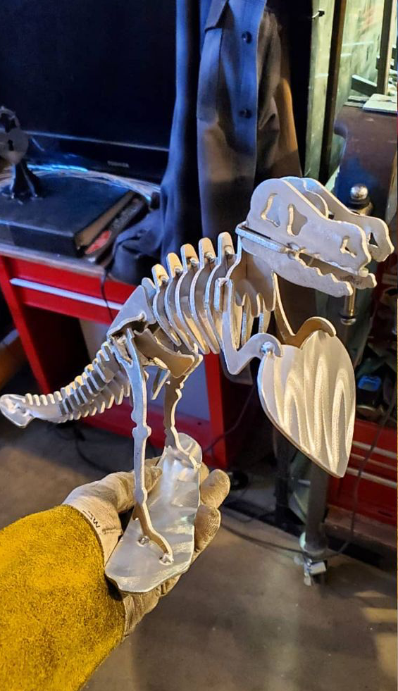
Got the new rex made . although my plasma is not set just right and beveled the slots. Minimal grinding fixed it. Its 20 percent larger so I made 1 thou. Clearance I thought the 1.2 upscale would be plenty of clearance for my 12 gauge. Thank you for the lessons. I didn’t see one youtube anywhere close to explaining this
.
1 Like
You’re welcome.
It’s one of the reasons I post here is because when I was learning there wasn’t that much info.
Please post pictures of your project when you get it cut and then put together.
1 Like