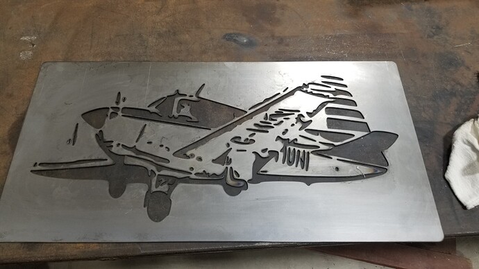
On simple parts it seems to work great, but this is the second time I have resized a larger part in fire control and it will not cut. It goes to the first pierce point, fires the torch and freezes. When I scale my drawing down in cad and repost with sheetcam it runs fine ? Any I missing something, or is this a common problem. It would not be as annoying but without home locations, losing my work offset makes for some waisted material. Luckily this part was forgiving.
when you resize a larger part on FC you do not get to see the actual problems you get when you resize in your design program and re postprocess…
here is an exaggeration of what happens when you just scale down a drawing and do not review the kerf width and finer details
you can see that the tool path does not get into the fine details and just cuts it rough…
this is what I believe is happening to you…
some basic shapes and paterns are easy to scale down…but when you scale down to far you loose the ability to get the fine details cut
The concept makes sense, although that really limits the usefulness of that feature. I could see if I was scaling down 50percent but I went from a 16in part width to a 15.4 in width.
I just had a thought… I wonder if the .07 arc on movement is getting scaled down too and possibly causing a comp issue on the g2-g3 line ?
it does not take much for the reduction to screw up the cuts…I have played with that a lot…making snowflakes…and even reducing it 1% can screw up the fine cuts
Lot less headaches in the long run to create different sizes in CAD and run SheetCam on each one. Its amazing what will disappear from the slightest reduction.
when I do drawings I run them through sheetcam…the ability to spot problems with the kerf width and all the extras make sheetcam a fantastic asset for saving metal
Thanks @LesNewell
You can also make the line thickness in your CAD program equal to the kerf. It won’t actually try to cut thick lines as the CAD GCode is based on the center of the visible line in Inkscape or AI or whatever. But you’ll be able to see where the kerf will overlap other cuts. Just set line thickness to .06" and the “line” will show you what your cut will look like.
another great idea by the world class Mr. James…never thought of that…

