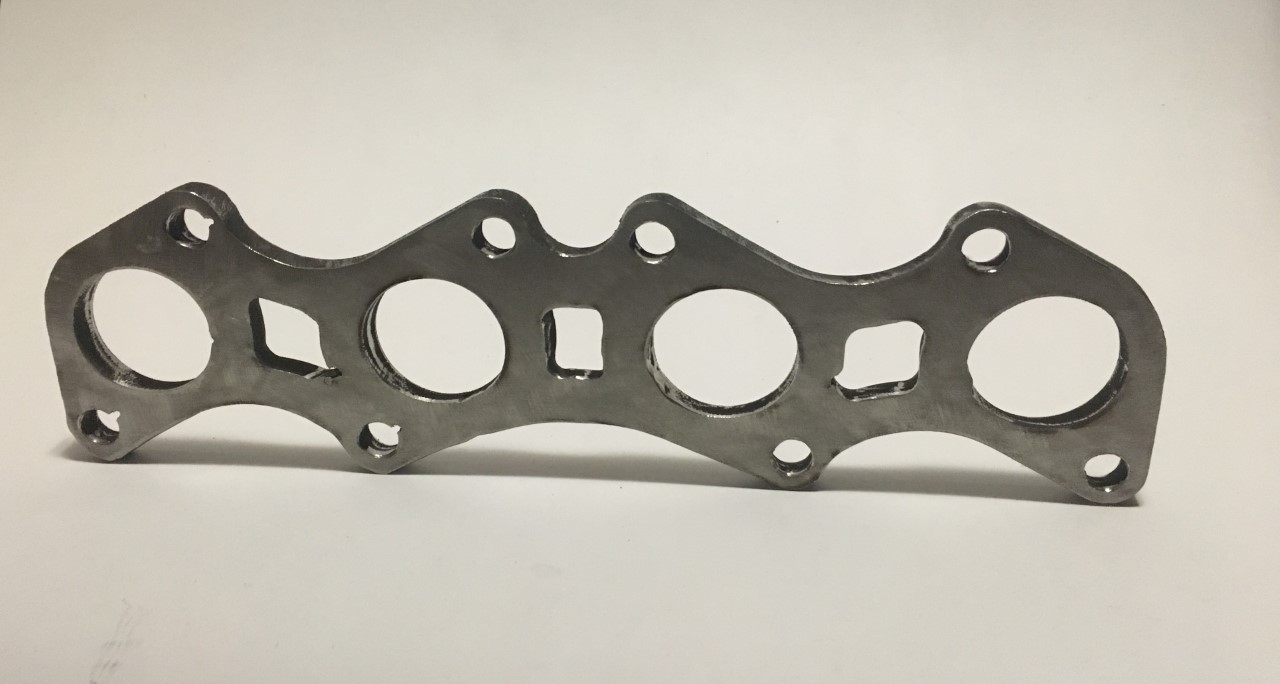
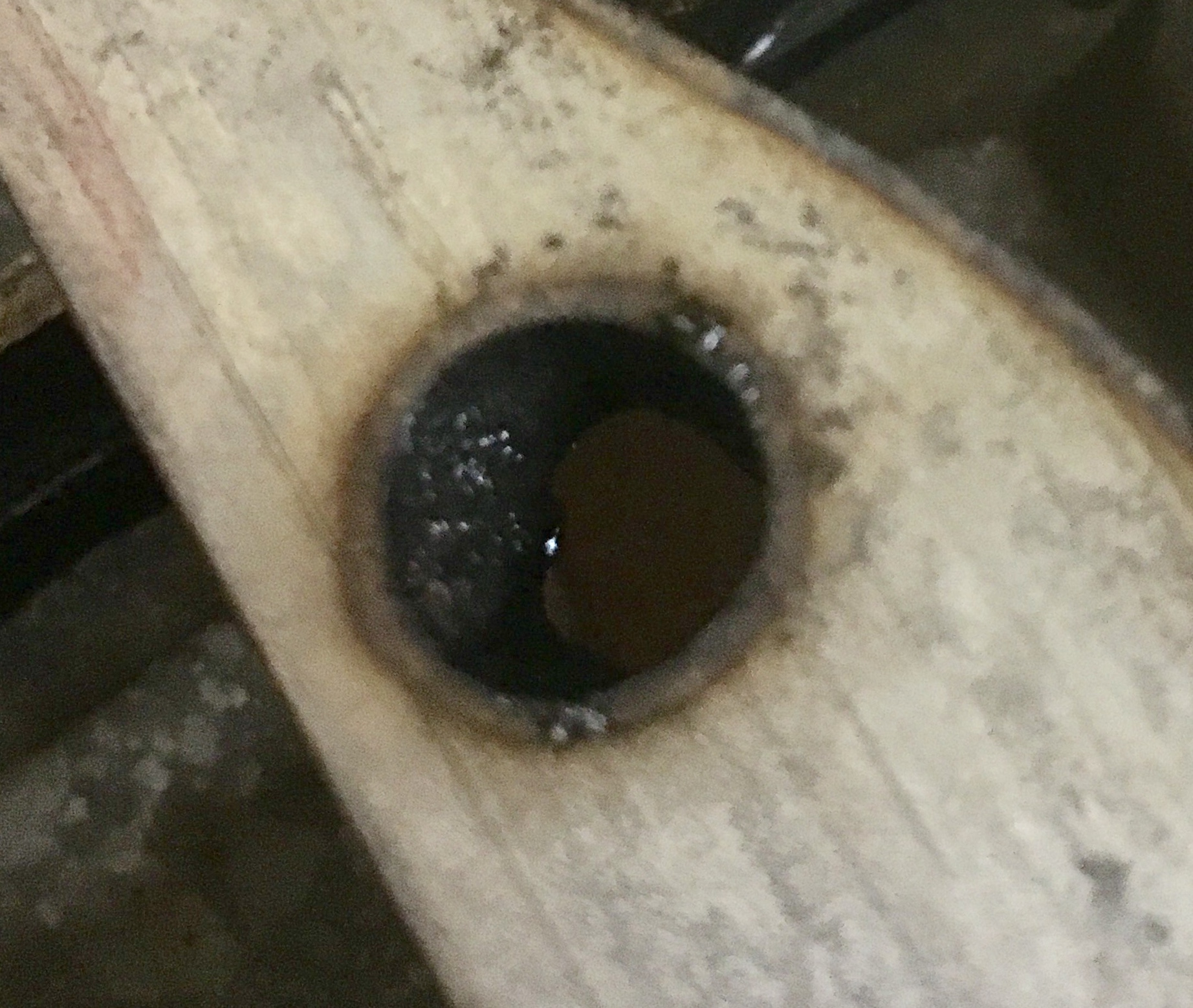
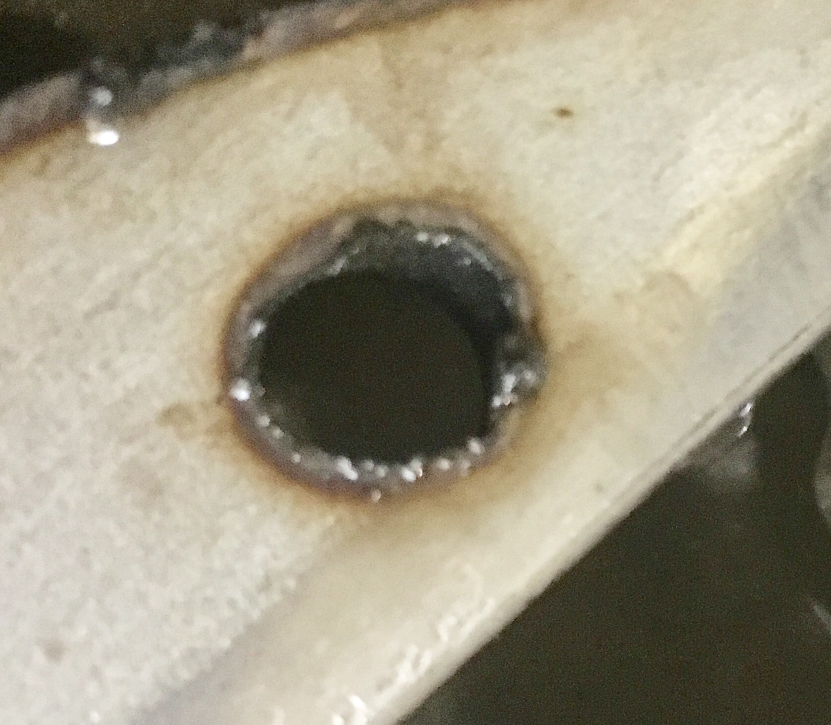
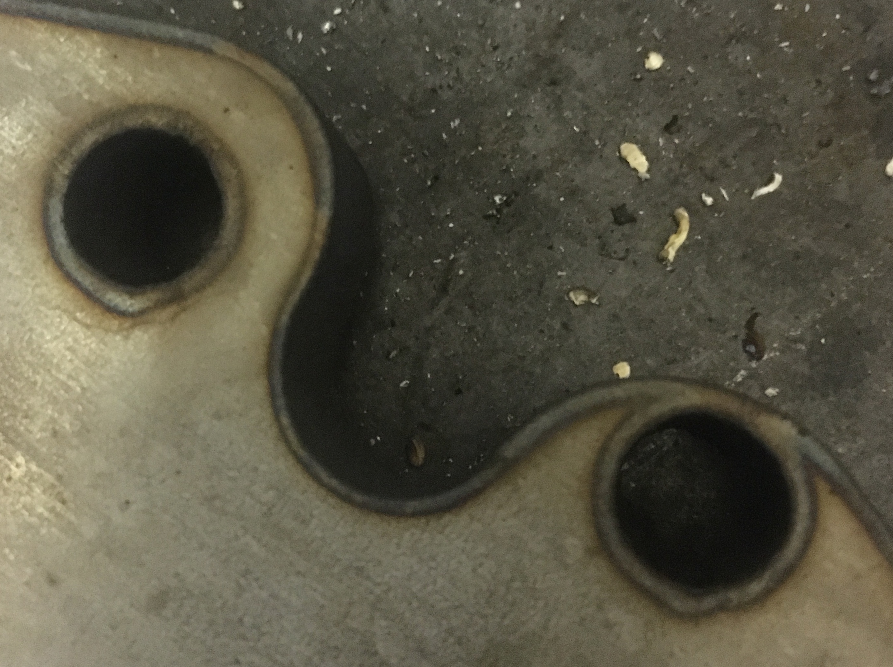
As you can see most cuts are ‘‘clean’’ but others have alot of deformation. Since the pierce delay, speed and lead in are all the same, what other settings could cause these issues ?
Couple of the large holes appear to be slightly out of round like make the lead screw is slipping inside the lead screw couple, try tightening the set screws.
But also see what looks to be some cuts maybe starting on the outside not the inside when setting up the contour.
But possible a slipping lead screw putting it slightly out of the correct start position causing that also but I am reaching a bit.
Geometrically are all the holes in the correct spots?
Miller has some good tutorials and articles on their website too.
If you know a teacher or Hypertherm dealer, they have a really good set of educational materials (but fairly pricey if you’re not) that can help teach you all about plasma cutting. Excellent source and much of it applies to any machine.
Do you have the inside of that hole selected for the toolpath or the outside? Might be cutting outside the line instead of inside where you want to cut so it’s moving a kerf width outside which takes you too close to the piece edge.
I have the inside of the hole selected. I think that even If i had the outside selected, the center of the hole would be at the same place, but the diameter would be bigger which is not the case.
It really seams like the geometry is not good. I dont know if its a program/pc issue or the table acting up …
Still thinking lead screw
Maybe tight lead screw nut or binding in one spot throwing it out of time. Have you tied lubing both lead screws with light machine oil?
Binding in a spot would throw timing off and effect geometry.
If you share your tap I would cut from some lighter gauge and just to verify the file and cut. A have to assume though your programming is correct.
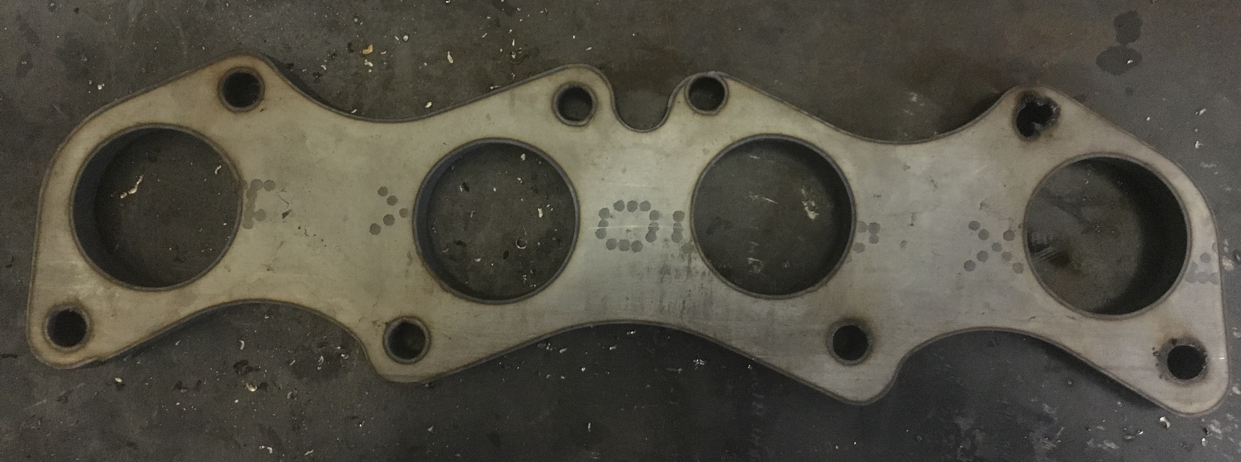
For the most part It appears your holes are now round (except maybe top right) but you bolt hole position seams off a touch on several locations to the right side.
Did you have much time on the machine before going to these parts? Tight bearing pre-load maybe effecting acceleration or causing drag. symmetry looks good to the left side but appears to shift up on the right.
I would have a hard time picturing the 3/8 plate moving unless it was a relatively small piece and some sort contact was made between the torch and the work piece. I assume you are cutting the perimeter of the piece last.
I have only had a work piece move when it was light gauge and made contact. I do however use some 3/8 plate on the edges of my work pieces to hold them in place. Just though of another piece that shifted on my but that was due to the perimeter cut just breaking through the outer edge of my sheet and that cause the sheet to pull close on one side. I learned from that.
If you have some mild steel (cheaper) you could zero the torch at another spot of the table. Maybe the front left corner. If it is a spot or an area on one of the lead screws for learning testing you maybe able to cut the part avoiding crossing over the spot.
You could also download a G Code viewer to look at you tap output file but I don’t expect the problem to be with the geometry itself. an online view is here https://ncviewer.com/
I just realised something, all my other parts that I cut were at over 100ipm (thin gauge) but since these flanges are 3/8 SS im running at 20ipm. Is there a minimum speed for the motors ? Or maybe there is juste more chance of binding/sticking at lower speeds.
I think you’re probably right about that. If you mirror the part does it do the same thing on what was the bottom (but the same place on the bed)?
I’d check the coupler set screws too. You could try running it with the plasma cutter off so it doesn’t fire and skip in the G-code to somewhere near that point and watch to see if the lead screws are moving smoothly or if there’s a hiccup caused by interference or a burr or something in that place on screw.
I’ve done that - but used one of those Velcro straps to hold it to the torch. Does all the travel lines as well as the cuts but it can be handy to see how a tricky piece will come out (& if something fails you can cut manually ).
Knowing the order of the cuts and the travel paths could be helpful
Looks like all four bolt holes to right side appear high and the tube hole on the far right looks high and to the right.
I do think I would like to rig sharpie for the future. Perhaps in a tube with light spring. Then tape or zip tie to torch.
Either way I hope he gets it worked out before burning too much stainless
why don’t you get some 1/4 mild steel and try it on that first. Eliminate some variables and save some money. I get drops of 1/4" 6x21 for $3. Then work your way up to 3/8 steel then go to your stainless. Also I’d make another cut file that orients the cutting the opposite way you are now on the machine. Or atleast move the part to diff part of the table. I had a a 6x21" piece of 1/4 move on me, did the same exact thing there, moved the hole where it wasn’t suppose to be.
have you noticed having to increase your pierce delay on your everlast?
 ).
).