I see the vipercut 30 does not have any guide to get you started on amps and metal thickness to give you a good start on cutting nicely. This is my first plasma much less a cnc plasma. Everything I run turns out like garbage and I am wasting material trying to get something to look right. I saw online that someone ran a line test with just multiple small lines cut in a row with different settings to see what looks best. How do I set something like this up? I am not sure how to set multiple inch per minute increments in Fusion in the same drawing. I am cutting pretty thin material since I only have a 20 amp breaker in the garage and when I turn the cutter up to 30 I trip the breaker after about 45 seconds.
So in Fusion 360 you would set up a drawing with a bunch of lines parallel to each other. Each line would then get its own tool. Each tool would have a different feedrate dropping down in 10 inches per minute increments. You can start with 20 in per minute increments then find the cuts that produce the best quality then go to 10 in per minute increments. Then you will find the best feedrate that produces a quality cut at that amperage and thickness. So say you’re on 16 gauge material I would start out with a feed rate of 150 inches per minute and go down to 50 inches per minute. If you have five lines each line would then be in 20 inches per minute increments then find the two best looking cuts then divide that feedrate into five different lines at 10 in per minute increments. Then keep doing this until you find a cut that produces the best edge quality with little dross. Your mileage may vary based on starting amperage. But do not change the amperage during the entire line test
5 Likes
Awesome! I’ve been wondering how to change the speed while cutting on the same iteration, makes sense and this helps out a lot!
Also when you export your g code make sure you have the “setup” selected. This will post all the 2d profiles instead of just one at a time.
1 Like
So i run a set up for each line and that will allow me to do the different speeds? I will play around with it this weekend and see if i can it to work.
I am not sure what I am doing wrong I put in 5 2 inch lines. I did a 2d profile for each line separately but when I generate the tool path it starts way out in the middle of nowhere. I have tried to redo it and fix it but it makes the problem worse. Is it possible to get a step by step to set up a line test in Fusion?
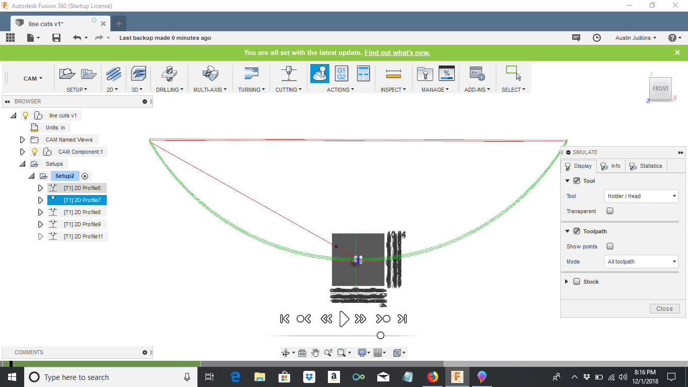
Draw a square 3x3 inches. Draw your (5) 2 inch lines inside of the square. Go to cam and click new setup. Make sure your home reference is set to one of the corners. Create a separate 2d cut toolpath for each line. Each toolpath has a different feedrate. Once you have 5 cut paths, create a 6th for the square. Cut the square out at a really slow feed rate so you know the square will actually get cut out. Select the setup that you created, usually setup 1, and click simulate to make sure it doing what it should be. With setup 1 still selected click post process. Save the file and then open it in mach 3. Should be good to go from there. If you only click one toolpath then post, it will only post that path not the rest of them.
1 Like
Do you have any insight on why my tool path generates way outside my parameters?
Probably because the home reference wasn’t set correctly. Make it the lower left corner (or any other corner, I just find the lower left convenient).
I did do that. It shows the x,y in the lower left right where the first line begins. When i hit generate path or simulate it begins the line way out left at the 75,100 coordinate or something. I checked the drawing for extra lines but nothing is out there.
Can you post the file? I can take a look and see what’s up.
Here is a link to the dropbox with a export from fusion 360 and a tap file. I am not sure how to attach things like that on here.
I think there’s something wrong with your origin setting.
When I look at your TAP file you can see that it’s going way off outside the machine’s physical size. See this line in your TAP file - N20 G0 X-78.0407 Y45.198
Whereas when I generate the toolpaths & g-code I get this:
N20 G0 X-0.0984 Y0.198
As a result you get a boatload of g-code out there in the middle of nowhere. But when it gets to Profile 2 (your second path), it looks like this:
N2030 G0 X-0.0984 Y0.698
That’s doable by the machine. You’ll notice too, that the g-code in your file for Profile 1 has many more lines than the same operation for Profiles 2 - 5. Your Profiles 2-5 in fact look pretty much like mine.
I also use some settings that weren’t in your F360 file -
-
In the passes tab of toolpath - Compensation type=In Control (I use In Computer)
-
In the linking tab of toolpath - Keep Nozzle Down=unchecked (I check it, specify 24" for max stay down distance, 0.1 cut stock clearance, uncheck force retract, staydown feedrate=300) since the Crossfire doesn’t have Z control; Entry position - you have Nothing & I pick a point on the line to give it a starting point.
Here are a couple of files I generated. I used different speeds than you did (20, 40, 60, 100, 150) but you can see what I did vs yours. Were you selected on the Front face when you created your setup? The F360 file opens up in the x/y/z corner view. I selected Front and then did my setup. But I also did it from your view and it still came out right for me.
I’ve uploaded the 2 files for you to look at - the Fusion file and the TAP file. I had to change the filetype to fool the forum (it only allows png, svg, dxf, jpeg). Just download them (right click and select save as) and delete the .dxf off the end of each and then they should be good.
Line test recalc v0.f3d.dxf (88.4 KB)
Line test recalc v0.tap.dxf (1.3 KB)
I had saved a DXF off the net and this is what I did. This is a 6"x6" panel and cuts 12 lines, in this sample the left line starts out at 20ipm increasing by 5ipm on each line so the right line ends in 75ipm. You could use this one and just change the feed rate for your what you want to test. This is just a baseline drawing the IPM can easily be changed for different thicknesses. I am sharing these but make sure you check it before running through a simulator before you run on your machine.
1 Like
Awesome thank you for the help everyone. I will put this information to use and see what i come up with.