When I cut out holes for bolts etc, I’m finding them to end up just a tad too small. I drew a .51 hole in fusion, but I then need to still hit with a drill bit for bolt to go through. This happens to all small holes for bolts. I’m only cutting .045 aluminum and even thinner steel. Do I need to oversize holes or something else going on? I’ve used the kerf width from tutorial and 30 amp viper cut at 30amps. Brand new consumables make no difference. 75psi air pressure with very dry air. Looking for some help
Yes, you need to compensate for the taper that is formed when cutting holes.
1 Like
So if you wanted a .5 hole in a piece of .045 aluminum, what should I draw for example?
I would measure the bottom size of the holes that you cut to make that determiantion. For example, if you program a 1/2" hole, and the bottom of the hole is measuring .460", I would program the holes to .550" to ensure the bottom of the hole measures about .510"
1 Like
I always clean out any holes I cut with a drill bit anyway. Just seems like it makes for a cleaner hole. a lot of the holes I do I end up countersinking a little bit and then I sandblasting entire piece looks really nice when I’m done. It’s an extra stuff but I have a drill press and it goes pretty quickly
1 Like
I’m thinking maybe the kerf width is wrong. I have a friend with the same machine and cuts much thicker metal for 4wd brackets. He says he draws .5 hole and it cuts .5 hole. Says when consumables wear, it starts not cutting quite right. I just would think with thin material like .023 or .045 aluminum that the hole should be correct size. What’s the best way to figure out kerf size for defining tool since vipercut doesn’t tell those specifications? Do I need to check with each 10amp adjustment? Does cut speed have anything to do with kerf width?
Theres really two different kerf widths for every cut. There’s the kerf width at the bottom of the cut and the kerf width at the top of the cut. The bottom kerf is nearly always smaller than the top kerf.
Traditional practice is to program using the top kerf width (and the way that I program as well). When i cut a 1/2" hole, the top of the hole is always nominal 1/2" and the bottom of the hole is something smaller (i.e. .450"). When I am making a part with a bolt pattern, I account for the taper and draw the holes larger than the size of the bolt using the logic in my last post.
It’s likely that your friend is programming using bottom kerf width. In other words, the bottom of his holes are 1/2" but the top are larger.
Counter to what you might think, cutting thinner materials yields more severe cut edge angularity. My best cuts with respect to edge angle are with 3/8" and thicker. I find the worst edge angle occurs with 14 gauge.
The best way to determine the true kerf width is to cut out a 1" square with kerf width set to 0. If the top width of the part measures .970" for example, then the top kerf width is .060".
1 Like
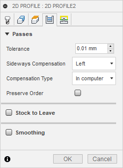
Also in Fusion 360 under the passes tab for your cam make sure compensation type is set to in Computer. The controller doesn’t compensate for your torch kerf. Fusion 360 defaults to in controller, this can throw your hole size off.
Yes sir, thats also correct.
Unrelated, but I really wish the default compensation type was set to ‘in computer’. Oh well!
1 Like