I have created a drawing and created all my toolpath setup excetera ready to cut and it is actually going to cut on the backside of the material. Is there any way to flip the drawing front to back after you create your toolpath so it cuts on the desired side you want after you get you’re drawing & tool path created?
not sure how it came out this way but I really do not want to have to redraw the whole thing, but I would like it you cut with a torch on the top side rather than the bottom side. I would rather have to deal with the drawers on the back rather than on the front. Not sure if I’m clear enough on this…
You could either rotate the image. Highlight everything, press “M” key, rotate 180 in the y direction I believe.
Or you could draw a vertical line next to your drawing on the left or right side but not touching. Go to the sketch drop down and select mirror. I forget which comes first but select the vertical line as your mirror line and then select your drawing as what to mirror. Press enter. Delete what you don’t need.
2 Likes
in addition to @Burgs04 method, you can do this in Mach3 as well - just enter -1 in the scaling for the x or y axis.
3 Likes
Much appreciated  Not what I did wrong. I will give it a try. Thanks!
Another interesting trick
When you do your setup in cam for your part set your Z+ up on the back of the part. You don’t need to change the drawing just the reference for the tool path. This makes cad so much easier because you don’t have to think backwards the whole time. Draw it normally and then machine it backwards.
If you need more details (screen shots, notes, etc) let me know I will post something up here to clear things up.
1 Like
@maleybr am interested. I just want to be able to get away from dross on the front of the part or project. Makes clean up so less tedious…
Top dross (spatter) is usually caused by a worn nozzle, too fast a speed or too high a torch standoff (shim height).
The plasma arc swirls and at to high a height or speed it tosses the material in front of the cut vs down through the material.
To fix it, check your nozzle, slow down (try 5 or 10ipm at a time - you can do that on the fly in the Mach control panel) and check your standoff - if you’re using a shielded tip & the standard thin shim you’re really higher than recommended because the shielded tip is usually a 1/16" standoff so you’ve doubled what you think you had.
Would you mind sharing how you adjust the cut speed in Mach? That would save me so much time when changing materials or experimenting and tuning in my cut speeds!
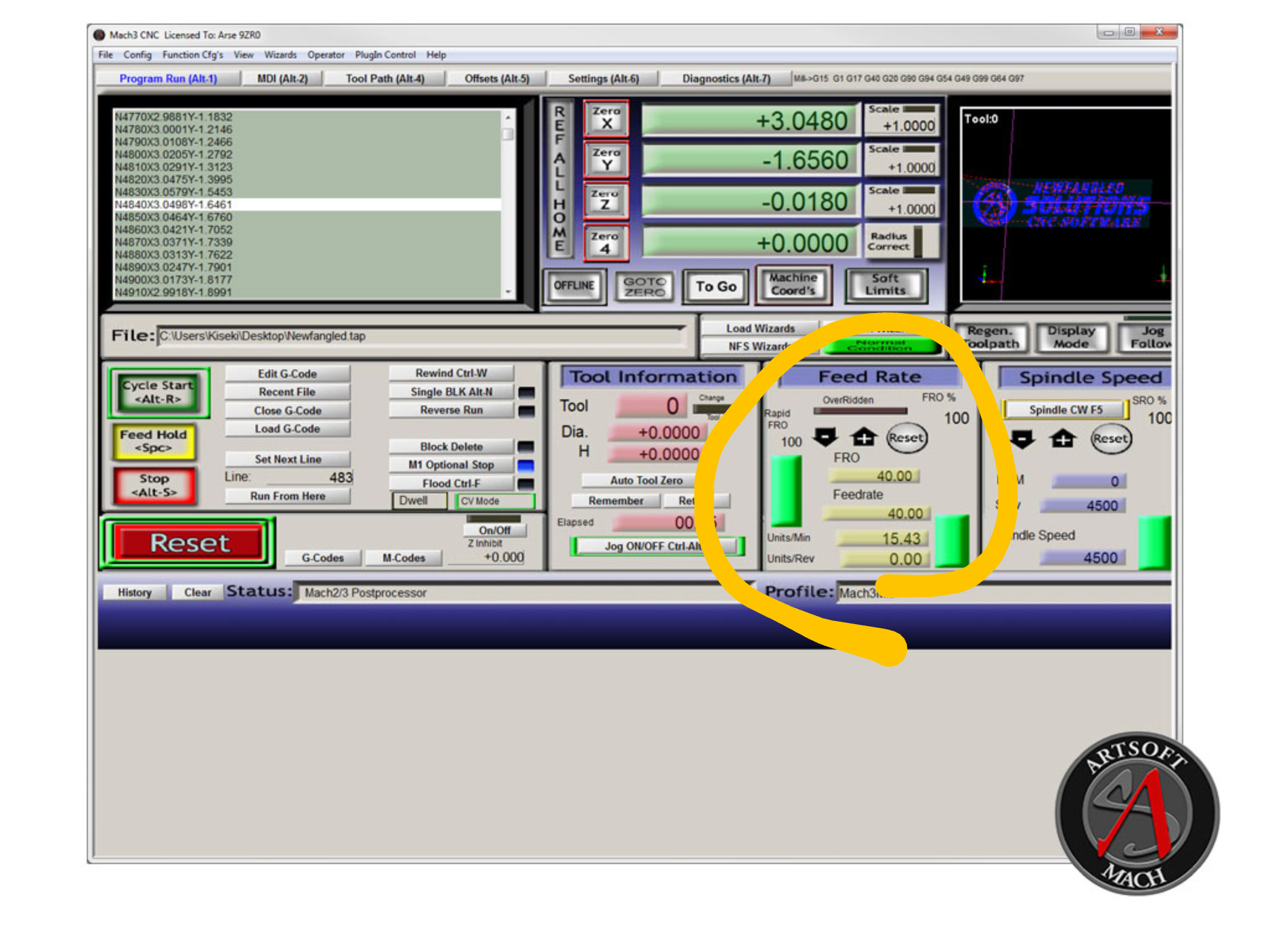
There’s a boxed area called “Feed rate”. You can use your mouse to drag it slower or reset it back.
When I use a new thickness of material I usually set the job up with higher than I’m like to use speeds (like 200) and then start slowing it down while watching the plasma arc so I can tell what the cut is doing with regard to spraying sparks which tells me if I’m too fast or too slow.
Here’s a pic of the Mach3 control panel. The feed rate section is the one I circled.
1 Like
@jamesdhatch Thank you for explaining and showing, I don’t recall seeing the +/- arrows on mine, just where it displays the cutting speed. I will give it a try when I get home, Thanks again for the Help!
Just above the feed rate I circled are boxes titled “scale”.
By the way, a negative number in the scale will mirror it around that axis.
Oh okay yeah used it before, just not z axis
Mirroring in Fusion using a line seems to be the best route. That way you have it done and dont have to reset it each time and you know it’s always right.
True enough if you want it to be that way in your design vs wanting to do just a one-off mirrored project. Then it’s quick and easy to flip it in Mach. Just another tool in the toolbox.
1 Like
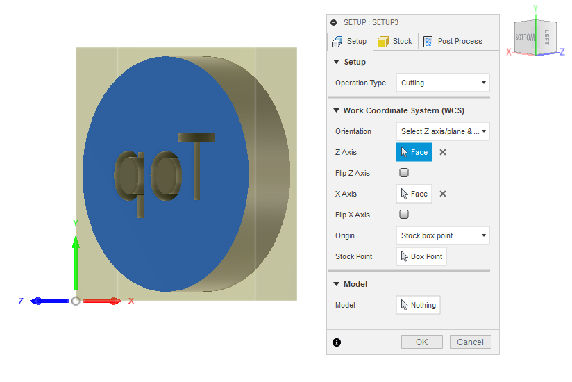
In Fusion if you go into the setup for your cam (right click on the setup and select edit)
On the first tab (setup) you will see the work coordinate system (WCS) for zaxis select face and click on the bottom face of your model. You will see X and y Stay the same and Z flips making the “Back” of the model the top. You will need to re-generate your tool paths for each step when you changed the WCS. That’s easily done by right clicking on the step and selecting generate from the drop down.
Post process and cut like normal.
Sorry it took so long for me to post this, it’s been a busy few weeks.
If there’s more Q’s just post I’ll try to reply quicker.
1 Like
NP, Thx I will give it a try and see…