The Sheetcam TNG version https://www.sheetcam.com/Downloads/akp3fldwqh/SheetCam%20TNG%20setup%20V6.0.28.exe I just starting getting into it more than just generating generic tool paths. Cut my first program today using some of the path rules where you can slow the IPM setting down by a percentage on things like small holes or shapes and inside corners to get more square inside cuts. Still have a lot to learn but with Sheetcam its a LOT simpler to learn these new things over Fusion and I have never had Sheetcam crash or lock up like I was constantly battling Fusion on.
Thanks,
Is this the limited version or the purchased version? It seems on their website that this is the limited version with 180 line max . I want to purchase the complete version. Is is like Mach3 that you download the trial version then upgrade and get the license sent to you?
Bev
Yes this download is the Demo, limited to 180 lines. You can download and install and then go to Sheetcam.com and on the side click Purchase and fill in the blanks, pay with Paypal and you will get a license emailed to you. Then in Sheetcam click on Help then Install License file and you are off and running.
I’ve been watching the 1st tutorial and the guy is saying you should install on the computer that’s on the table. I’m assuming he’s talking about the computer that’s attached with the USB cable to our Crosfire table correct? Did you need to add any of the extra parameters to your download to make it work from the computer connected to the table?
I just want to be sure in case I need to watch that installation video as well.
Bev
I cant say I fully understand the question. The electronic enclosure is the box mounted to the frame just bellow the Y axis stepper motor. The USB cable connects you PC or laptop to this and this then interfaces with your stepper motors.
The computer that then runs the table (may same computer you use for fusion) assuming it is dedicated to table.
This computer needs ;
-
Mach 3
-
CrossFire Mach3 USB Motion Controller Plugin (v1.0). Download and move into Mach3 Plugins folder (Usually C:/Mach3/Plugins)
-
CrossFire Mach3 Profile (v1.1). Download (Right-click, ‘Save Link As’) Move into Mach3 folder (Usually C:/Mach3)
Now when you launch Mach 3 you will first see a Profile Selection box. If the CrossFire Mach3 Profile (v1.1) is in the correct folder it will see it in this box and can select it as an option and click okay. You can delete the other profiles in the box for less clutter.
I hope this helps.
Also this question should have gone into a separate topic as it is off topic for this thread. 
1 Like
Continuing the discussion from FRUSTRATION FUSION 360 Importing DXF:
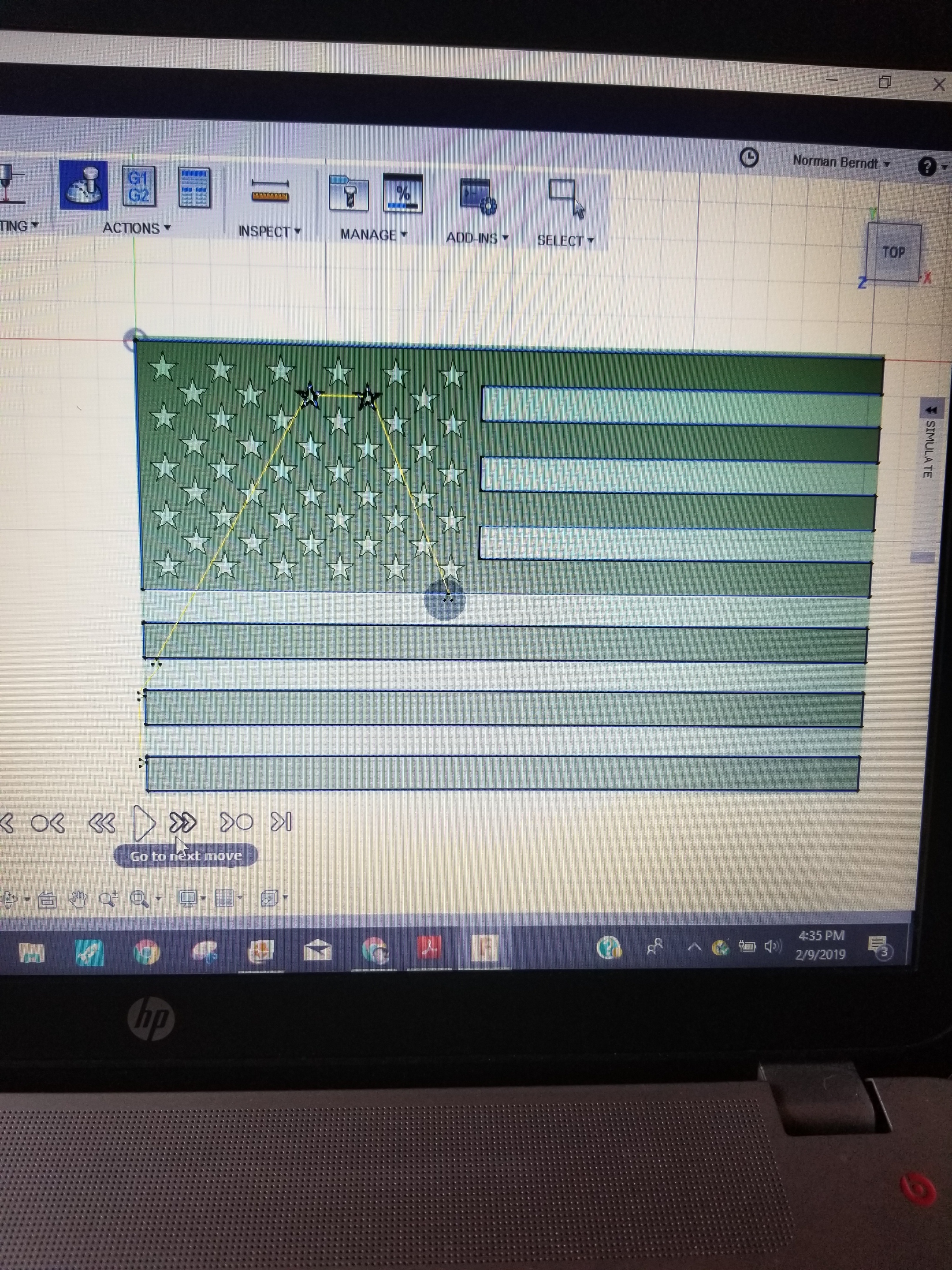
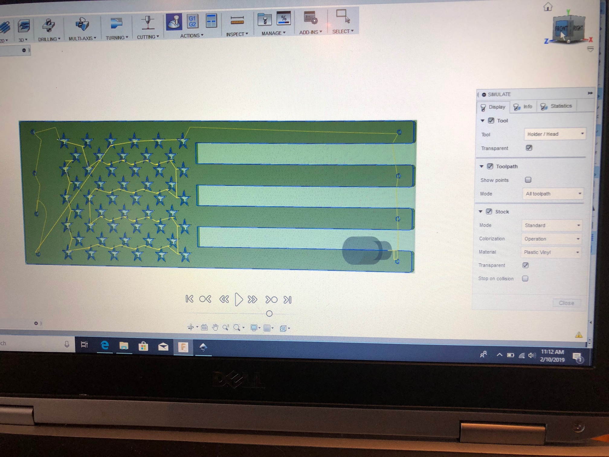
Ok, so i’m making my way thru the process. Why would my extruded image include all 50 stars (American flag) but my simulation only show 2 stars being cut?
Also, I can’t seem to find the video showing how to move my sketch from one plane to another. In the videos it shows the XY being the front plane. On my Fusion360 it is the top…
Front plane should be XY
When FUSION WAS done generating the tool path did you have any message errors?
Like a yellow triangle nest to your set up
Might have dropped a lot of the cuts do to some constraint or Cam setup you have it csnnot perform.
Like too much lead in or out etc…
If it see something where the current torch tool paths wont work with the current setup it will not generate a tool path.
1 Like
She’s on xy
And all stars extruded properly, which in would think means the toolpath should be good?
They extruded properly
But in Geometry when you selected the face to machine did it clearly show all the RED ARROWS
in counter clockwise direction in every star?
I did get an error! It was just over on the left under setups, instead of the lower right where i’ve seen them before.
Warning: One or more passes were discarded due to linking constraints.
Generation completed with 1 warning(s) in 8.8s.
So most all off the stars are red with blue arrow pointing inward to center.
One has no arrow???
And one has the arrow pointing outward.

All the interior cuts ie. the Stars, should have. Blue Arrow showing a counterclockwise rotation for the cutter not clockwise.
The exterior profiles cut clockwise.
Your error mostly means something in your Cam setup can’t be done with your current settings.
The exterior profiles cut clockwise.
Your error mostly means something in your Cam setup can’t be done with your current settings.
Make sure settings are left And in-computer compensation.
& if you want FUSION selecting your geometry for CAM toolpathing you need outside selected not inside.
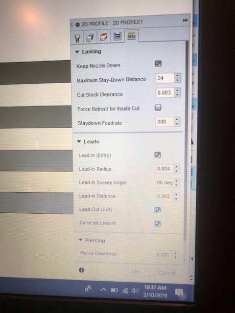
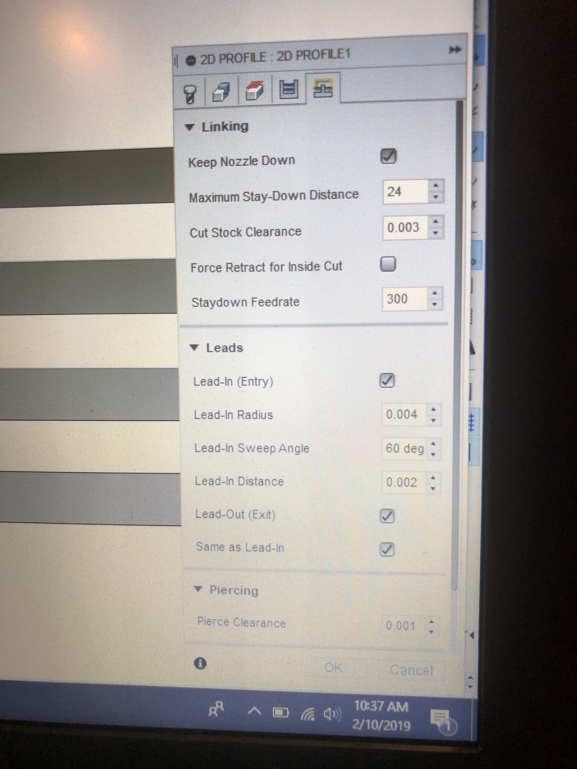
Lead in , lead out , material cleanace , pierce clearance etc. maybe be to large for fusion to tool path those stars , ie. it can’t fit inside with any or one or more of the settings.
When I design a sketch I set my stoke line width in INKSCAPE to the Kerf width of my cutter nozzle. In my case I’ve been using .6 nozzle which gives me a .025” kerf width approx.
Then I can see if my cutter can fit and not melt away areas when it would cut
Then I SAVE the file as a dxf with the stroke set back down to .001”
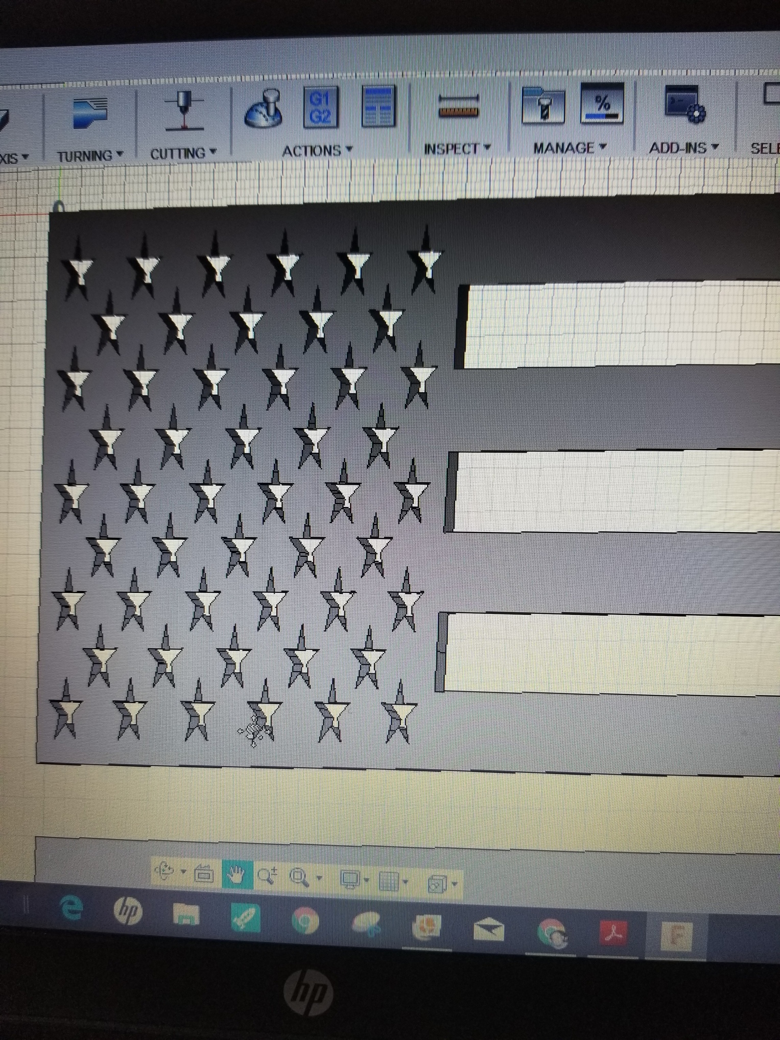
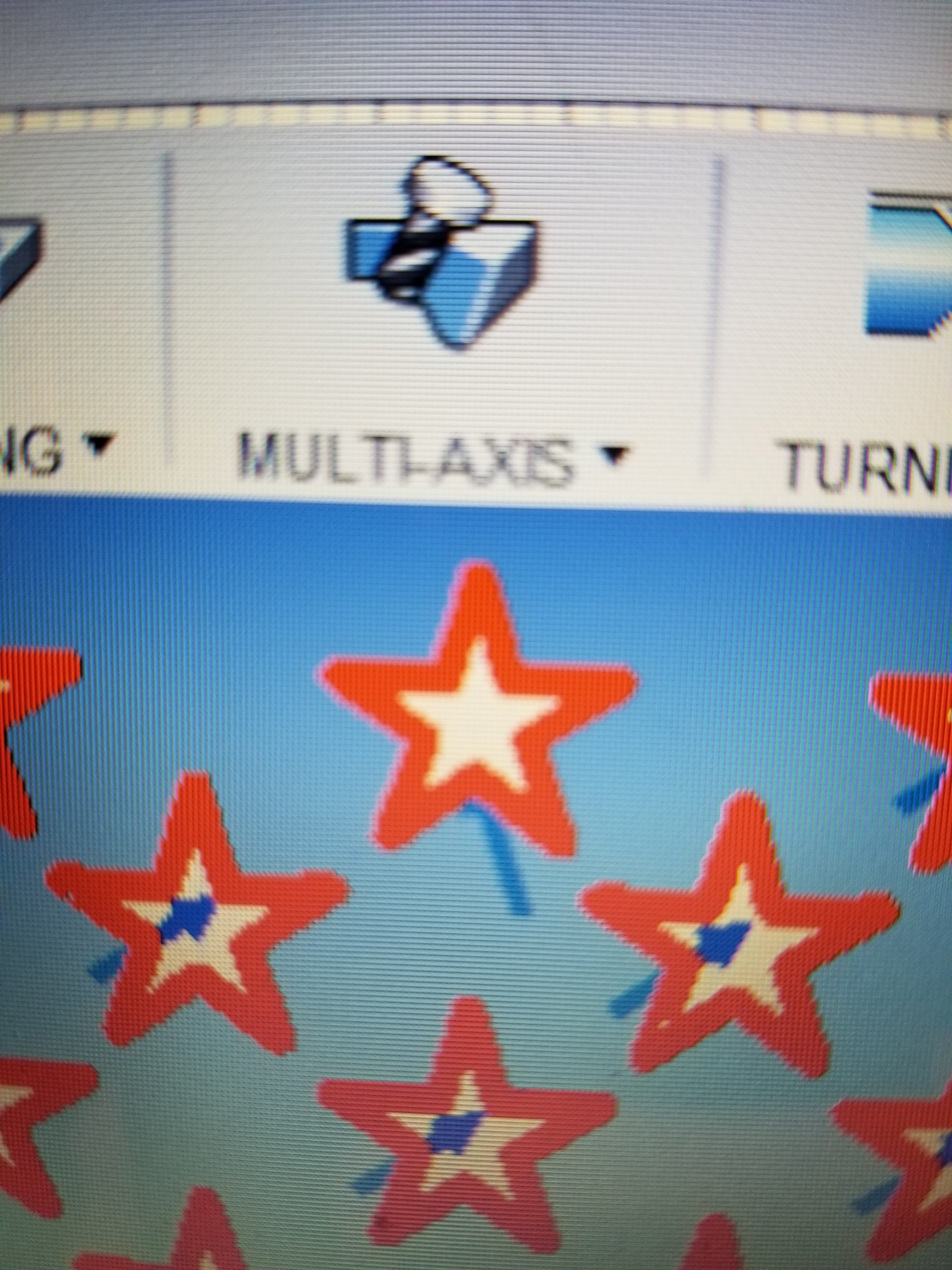
Zoom way in the the Stars and see if the Arrows are starting inside the stars.
They should be. And also indicating a counter clockwise Cut
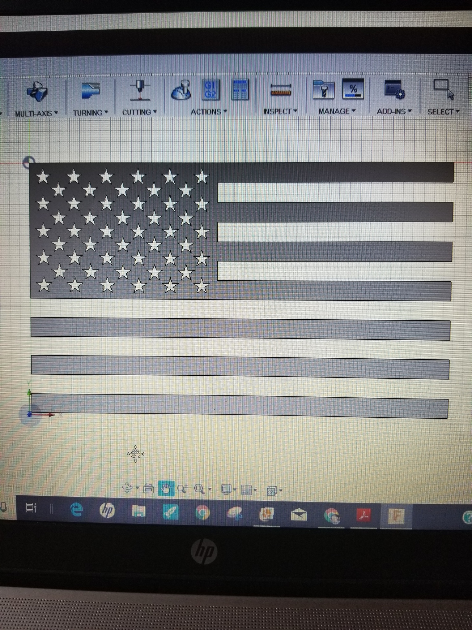
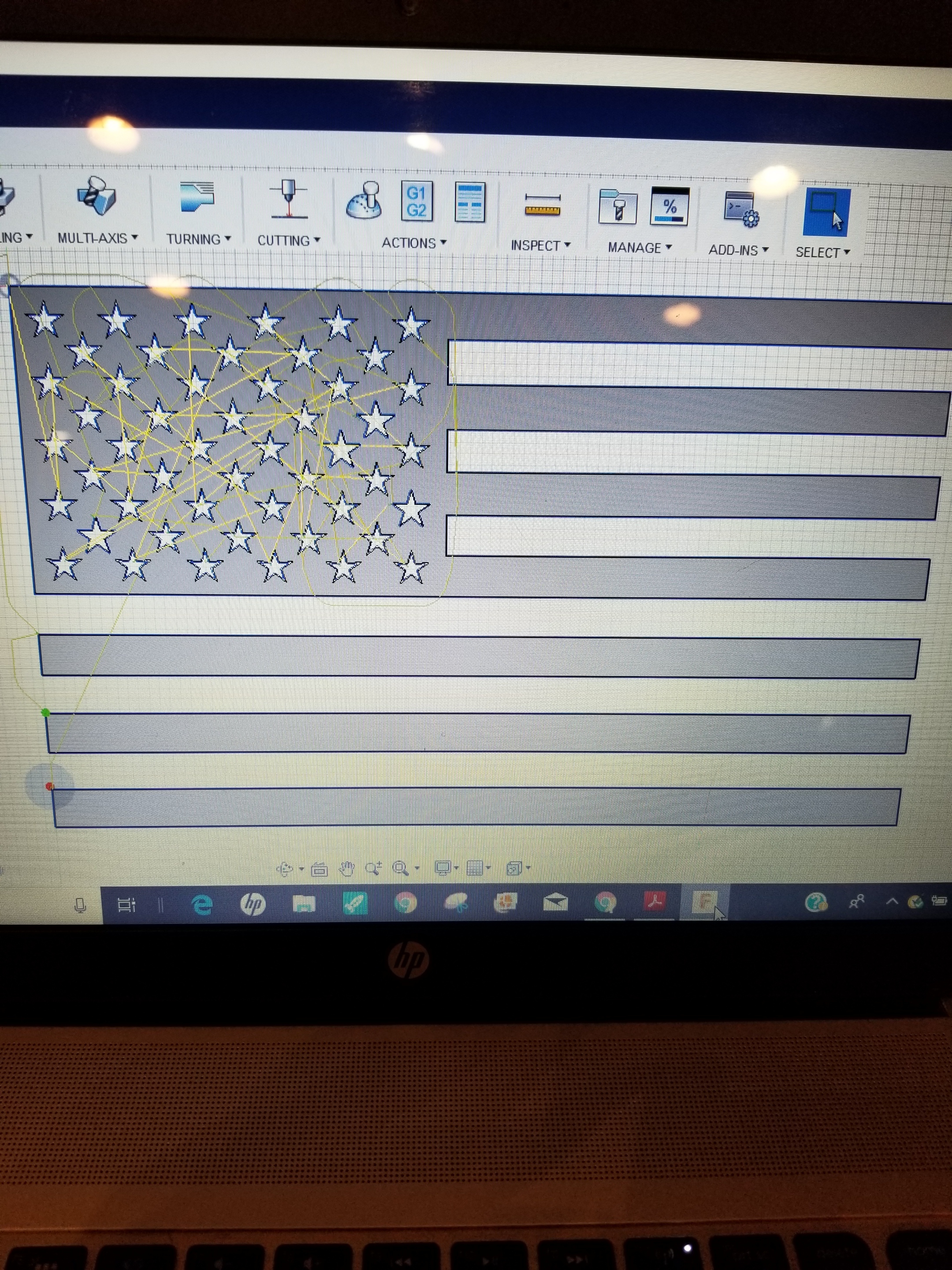
I inserted the LANGMUIR FLAG FILE
Set everything in Manufactuer and it simulated and toolpathed everything without issue.
Using my .6mm nozzle set up
If your on a .8 or 1.0
You’ll have to tweak the setup even more to get the cutter to fit with the bigger kerf width cut.
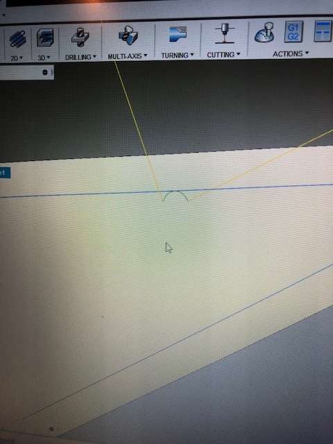
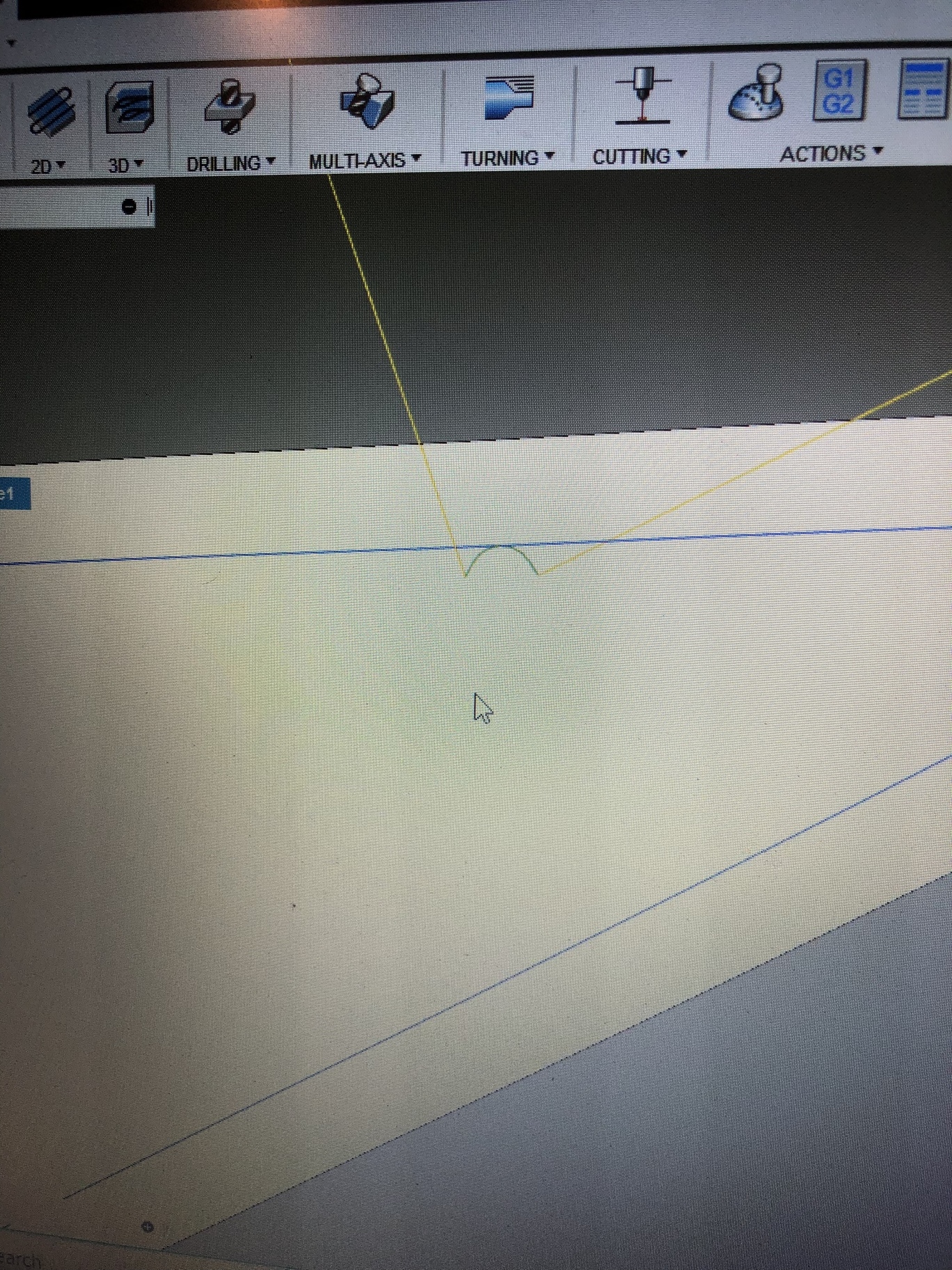
See photos
Zoomed up u can see the green arc with the lead in and arc in. And how these settings make it fit without fail.
You could go bigger with the lead in and cut stock clearance, I just wanted to demonstrate
That your settings and cutter if not Cam ‘ed properly will cause FUSION To error and delete
Some paths that simply will not work.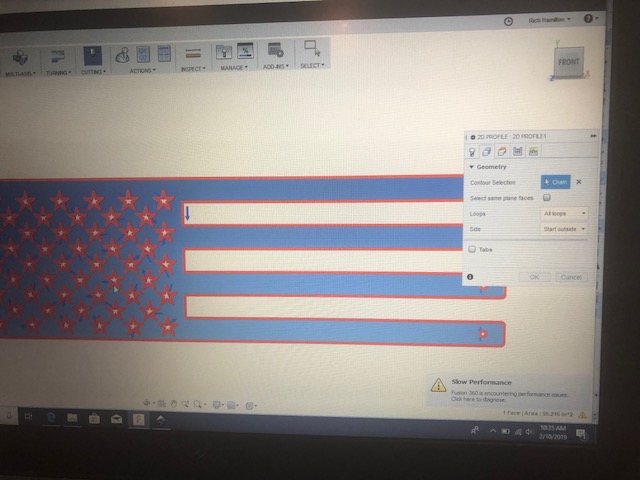
SIMULATION Ran fine as well
1 Like
Went back thru the videos and found where I missed several steps. Im going to have to create a cheat sheet because this is way more complicated than I imagined! Have made it thru post processing now.
I ordered the full version of Mach3 and will begin the downloading and licensing process next! Can’t wait for my machine to get here and get it put together!!!
 On the cheat sheet. I just made up things to do in fusion to go through the steps then deleted them. I still sometimes forget to make the project into inches from mm when in manufacture. My cheat sheet says across the top n huge letters ( SET TO INCHES IN CAM) Now cam is manyfacture of course. Glad your working it out.
Thank you PWCNC,
I know this is an old thread but, it has solves a big problem for me and wanted to give you a shout out for this. I have a Maple leaf that I was trying to cut out of 20 ga SS, but there was so much gcode that the table controller could not process it fast enough to run at 150 in/min. After reading this thread and making the suggested changes the gcode went from over 9000 lines to just over 1000 lines.
Another tidbit of information to go along with this is, if you want these changes to be your default every time you create a new document, you can change the default.svg file by doing the following:
• Open up inkscape - blank document
• Make the changes you want to keep, like what PWCNC posted above.
• Save the file as default.svg,
• Close inkscape
• Then in your C:\Program Files\inkscape\share\template\ directory (on my linux pc it is in ./config/inkscape/), Rename the current default.svg file to default.svg.org or something like that.
• Copy in the new default.svg file you just create.
• Reopen inkscape and you should have the new default settings in it.
Dan
1 Like
Haven’t cut anything for months
XMASS went crazy for wood CNC orders!
Thanks